How to remove the bypass valve to yamz 238. Lubrication system
Send your good work in the knowledge base is simple. Use the form below
Students, graduate students, young scientists who use the knowledge base in their studies and work will be very grateful to you.
Posted on http://www.allbest.ru/
Examination on the topic:
YaMZ-238 engine lubrication system
Engine lubrication system (Fig. 1) is intended for placement, cleaning and cooling of oil, supply of purified and cooled oil to rubbing parts of the engine in order to reduce their friction, wear, heating and removal of the resulting wear products.
YaMZ engine lubrication system- mixed, with a "wet" sump. The oil pump, through the suction pipe with the intake, draws oil from the sump and feeds it into the system through a series-connected oil filter.
Lubrication system includes:
· Engine pan
· Oil intake
Oil filters
· Turbocharger oil filter
Radiators
· Oil level gauge
· Instrumentation
· Highways and pipelines.
Fig. 1. Engine lubrication system: 1 - air-oil radiators; 2 - bypass valve; 3 - coarse filter; 4 - centrifugal cleaner; 5 - oil filler neck; 6 - vertical channel; 7 - central vertical channel; 8 - turbocharger filter; 9 - channel drain oil into the pan; 10 - turbocharger; 11 - central horizontal channel; 12 - pressure gauge; 13 - pallet; 14 - differential valve; 15 - radiator shut off tap; 16 - safety valves; 17 - pressure reducing valves; 18 - oil intake; 19 - radiator section of the pump; 20 - main (pumping) section of the pump
Engine pan, stamped from sheet steel, is a container for oil. The pallet is bolted to the bottom of the cylinder block and sealed with a 2.5 mm thick rubber gasket.
Oil intakeprovides primary oil cleaning and its supply to the pump. It consists of a housing with a strainer, a suction tube with a flange and mounting parts.
Oil pump creates the necessary pressure in the lubrication system and delivers oil under pressure to the rubbing surfaces of engine parts. The gear-type pump is mounted on the front main bearing cover; it consists of two sections, the main and the radiator. Both the main and radiator sections of the pump are combined in one unit and have two gears.
Coarse oil filter designed for 100% filtration of oil supplied to the rubbing; surfaces of engine parts. When the engine is running, oil flows through the left channel into the hollow central shaft 2 (Fig. 23). Through the cutouts in the upper part of the rod, the oil enters under the filter cap 4 and, passing through the filter element 6, enters the internal cavity of the filter.
Oil Centrifugal Filter It is intended for finer purification of oil from mechanical impurities with a size of 1 μm or more, the products of oxidation and resinification of oil. The filter is included in the system in parallel and passes about 10% of the oil entering the system. The filter capacity is 10 liters per minute at an oil pressure of 0.49 MPa (4.9 kgf / cm2).
Turbocharger oil filter Designed for 100% filtration of oil supplied from the central horizontal oil channel of the engine to the bearings of the turbocharger. It is mounted on the right rear air manifold and bolted.
Oil coolers. Two air-oil tubular radiators are installed in the engine oil system, which are connected in series. On the KrAZ-643701 car (YaMZ-238F engine), the radiators must be constantly switched on due to the fact that the oil in the specified engine is used to cool the pistons and bearings of the turbocharger and, thus, more intensively than in other models, is involved in heat removal from heat-stressed engine zones. The radiators are turned off by a tap mounted on the left side of the unit.
The lubrication system of the YaMZ-238 engine is mixed, with a wet sump (Fig. 1).
Fig. 2. Scheme of the lubrication system of the YaMZ-238 engine with a single-section oil pump and a liquid-oil heat exchanger: 1 - oil sump; 2 - oil intake; 3 - oil pump; 4 - pressure reducing valve; 5 - liquid-oil heat exchanger; 6 - oil filter; 7 - bypass valve; 8 - signal lamp of the filter; 9 - centrifugal oil filter; 10 - a camshaft; 11 - axis of the pushers; 12 - a cranked shaft; 13 - differential valve; 14 - piston cooling nozzle; 15 - valve of the piston cooling system; 16 - a turbocompressor; 17 - bypass valve of the heat exchanger; 18 - fan drive switch; 19 - fan drive; 20 - fuel pump
An oil pump 238B-1011014-A with a capacity of 140 l / min (Fig. 2) draws oil from the crankcase through an intake pipe with a suction pipe and feeds it into the system through a series-connected liquid-oil heat exchanger.
Fig. 3. Oil pump YaMZ-2381 - intermediate gear; 2 - an axis of an intermediate gear; 3 - drive pinion shaft; 4 - housing cover; 5 - driven gear shaft; 6 - case; 7 - drive gear; 8 - key; 9 - persistent flange
In the body of the heat exchanger (plate), a bypass valve is installed.
When the pressure difference before and after the heat exchanger reaches 274 ± 40 kPa (2.8 ± 0.40 kgf / cm2), the valve opens and part of the oil is supplied directly to the oil line.
From the liquid-oil heat exchanger, the oil enters the channel of the unit through a differential valve designed to maintain a constant pressure in the system.
When the pressure rises above 520 kPa (5.2 kgf / cm2), part of the oil is drained into the crankcase.
The valve of the piston cooling system stops the oil supply to the nozzles at an oil pressure in the lubrication system below 130 - 165 kPa (1.30 - 1.65 kgf / cm2).
The other part enters the oil filter (Fig. 3).
Fig. 3. Oil filter YaMZ-238 : 1 - filter housing; 2 - a lining of a cap; 3 - lock cover; 4 - filter cap; 5 - filter element; 6 - cap head; 7 - laying of the filter element; 8 - valve plug; 9 - valve spring; 10 - signaling spring; 11 - movable contact signaling device; 12 - fixed contact; 13 - terminal
A bypass valve is installed in the filter housing.
When the pressure difference before and after the filter reaches 200 - 250 kPa (2.0 - 2.5 kgf / cm2), the valve opens and part of the crude oil is fed directly to the oil line.
By the moment the bypass valve starts to open, the movable and fixed contacts of the signaling device will be closed.
At this moment, a signal lamp connected to the terminal of the signaling device lights up in the driver's cab.
Such an increase in pressure can occur when the filter element is clogged or the oil has a high viscosity (for example, when starting the engine in the cold season).
The filter element of the YaMZ-238 oil filter is made of either non-woven material stretched over a metal frame or special filter paper.
From the filter, oil enters the central oil channel, and from there through the channel system in the block to the crankshaft and camshaft bearings.
From the bearings of the crankshaft YaMZ-238, through the oil channels in the crankshaft and connecting rods, oil is supplied to the bearings of the upper heads of the connecting rods.
From the YaMZ-238 camshaft, the oil is sent in a pulsating flow to the axis of the pushers, and from there through the channels of the pushers, the cavities of the rods and the rocker arm to all the rubbing valve pairs, and through the outer pipe to the bearings of the turbocharger, speed controller and fuel pump high pressure.
Under pressure, the bearing of the intermediate gear of the YaMZ-238 oil pump drive is also lubricated.
The gears of the drive units, camshafts, rolling bearings, cylinder liners are lubricated by spraying.
A pressure reducing valve is installed on the front flange of the outlet pipe of the YaMZ-238 oil pump, which transfers oil back to the crankcase at a pump outlet pressure of more than 700 - 800 kPa (7.0 - 8.0 kgf / cm2).
To stabilize the pressure, a differential valve is included in the lubrication system of the YaMZ-238 engine, the adjusted opening start is 490 - 520 kPa (4.9 - 5.2 kgf / cm2).
Oil pressure control is carried out in the central oil channel.
grease engine pump radiator
Fig. 4. Filter of centrifugal oil purification YaMZ-238
1 - filter cap; 2, 7 - washers; 3 - cap nut; 4 - a nut of fastening of a rotor; 5 - persistent washer; 6 - rotor nut; 8, 14 - rotor bushings; 9 - a cap of a rotor; 10 - rotor; 11 - reflector; 12 - a sealing ring; 13 - a lining of a cap; 15 - axis of the rotor; 16 - filter housing; 17 - rotor nozzle; A - from the system under pressure; B - oil drain into the crankcase
The centrifugal oil filter YaMZ-238 (Fig. 4), included in the lubrication system in parallel after the oil filter, passes up to 8% of the oil passing through the lubrication system.
The YaMZ-238 filter is designed for fine oil filtration.
The oil is cleaned by centrifugal forces during rotation of the rotor.
The jets of oil coming out of the nozzle at high speed create a moment that drives the rotor into rotation.
The mechanical impurities in the oil, under the action of centrifugal forces, are thrown “to the wall” of the cap 9 of the rotor, forming a dense layer of deposits on its inner surfaces, which should be periodically removed.
Refined oil is drained into the crankcase.
Additional centrifugal oil cleaning is also performed in the cavities of the connecting rod necks of the crankshaft YaMZ-238.
Posted on Allbest.ru
...Similar documents
The operation of the oil pump and oil filter. The design and operation of the lubrication system. Scheme of the lubrication system of the oil pump, full-flow oil purification filter, centrifugal oil filter. Water-oil heat exchanger and crankcase ventilation system.
term paper, added 12/20/2010
The purpose, structure and operation of the engine lubrication system of the VAZ-2109 automobile. The main malfunctions, the causes of their occurrence and methods of elimination. Dismantling, checking parts and assembling the oil pump. Lubrication system maintenance.
thesis, added 05.12.2014
Kinematics and dynamics of the crank mechanism. Calculation of the details of the piston group. Gasoline engine cooling system - calculation of radiator, liquid pump, fan. Calculation of units of the lubrication system - oil pump and oil cooler.
term paper added 03/04/2013
Dynamic calculation of the engine. Kinematics of the crank mechanism. Calculation of the details of the piston group. Engine cooling system. Calculation of a radiator, a liquid pump, a fan. Engine lubrication system, its operational reliability.
term paper, added 02/27/2013
The layout of the crank mechanism. Engine cooling system. Engine temperature internal combustion. Diagram of a carburetor idle system. Work and the device of the fuel priming pump. Types of fuel filters.
test, added 06/20/2013
crank mechanism engine. The purpose of the piston fingers. The principle of operation of the pump of the KamAZ-740.10 cooling system. Lubrication system ZMZ-4062.10. The path of oil from the pump to the timing valve assembly. K-151 carburetor, accelerator pump system.
term paper, added 12/10/2011
Brief description of the internal combustion engine. The main moving and stationary parts. The device of the mixture formation and gas distribution system. Fuel system. Circulation system lubrication of the main marine engine, cooling system.
presentation, added 12.03.2015
Technical characteristics of the car MAZ-5551. The main design features of the lubrication system. The principle of operation of the lubrication system. Viscosity grades of motor oils. Oils for turbocharged engines that meet Euro-2 environmental standards.
term paper, added 04.12.2015
The device and purpose of the power supply system of the KamAZ-740 engine. The main mechanisms, components and malfunctions of the engine power system, its maintenance and current repair. Exhaust system. Coarse and fine fuel filters.
abstract, added 05/31/2015
Appointment, device and engine operation. Faults, diagnosis and maintenance of the unit. The procedure for disassembling and assembling the engine. Defect detection of parts with a description of methods for possible restoration of suitability for further operation
Mixed with wet sump ( fig. fifteen).
Fig. 15. Scheme of the engine lubrication system with a single-section oil pump and a liquid-oil heat exchanger: 1 - oil sump; 2 - oil intake; 3 - oil pump; 4 - pressure reducing valve; 5 - liquid-oil heat exchanger; 6 - oil purification filter; 7 - bypass valve; 8 - signal lamp of the filter; 9 - centrifugal oil filter; 10 - a camshaft; 11 - axis of the pushers; 12 - a cranked shaft; 13 - differential valve; 14 - piston cooling nozzle; 15 - valve of the piston cooling system; 16 - a turbocompressor; 17 - bypass valve of the heat exchanger; 18 - fan drive switch; 19 - fan drive; 20 - fuel pump.
Oil pump 238B-1011014-A with a productivity of 140 l / min ( fig. 16) through the suction pipe with the intake, oil is sucked from the crankcase and feeds it into the system through a series-connected liquid-oil heat exchanger. A bypass valve is installed in the heat exchanger housing. When the pressure difference before and after the heat exchanger reaches 274 ± 25 kPa (2.8 ± 0.25 kgf / cm2), the valve opens and part of the oil is supplied directly to the oil line. From the liquid-oil heat exchanger, the oil enters the channel of the unit through a differential valve designed to maintain a constant pressure in the system. When the pressure rises above 520 kPa (5.2 kgf / cm), part of the oil is drained into the crankcase.
Fig. 16. Oil pump: 1 - an intermediate gear; 2 - axis prom. Gears 3 - drive pinion shaft; 4 - housing cover; 5 - driven gear shaft; 6 - case; 7 - drive gear; 8 - key; 9 - thrust flange.
Further, through the channels in the block, part of the oil through the valve of the piston cooling system enters the piston cooling nozzles and then merges into the crankcase. The valve of the piston cooling system stops the oil supply to the nozzles at an oil pressure in the lubrication system below 130-165 kPa (1.30 - 1.65 kgf / cm2).
The other part goes to oil filter (fig. 17) A bypass valve is installed in the filter housing. When the pressure difference before and after the filter reaches 200 - 250 kPa (2.0-2.5 kgf / cm2), the valve opens and part of the crude oil is fed directly to the oil line. By the moment the bypass valve starts to open, the movable and fixed contacts of the signaling device will be closed. At this moment, a signal lamp connected to the terminal of the signaling device lights up in the driver's cab. This pressure increase can occur when the filter element is clogged or the oil has a high viscosity (for example, when starting the engine in the cold season).
Fig. 17. Oil filter: 1 - filter housing; 2 - a lining of a cap; 3 - lock cover; 4 - filter cap; 5 - filter element; 6 - cap head; 7 - gasket filtering element; 8 - valve plug; 9 - valve spring; 10 - signaling spring; 11 - movable contact signaling device; 12 - fixed contact; 13 - terminal.
The filter element of the oil filter is made either of non-woven material stretched over a metal frame, or of special filter paper.
From the filter, oil enters the central oil channel, and from there through the channel system in the block to the bearings of the crankshaft and camshaft. From the bearings of the crankshaft through the oil channels in the crankshaft and connecting rods, oil is supplied to the bearings of the upper heads of the connecting rods. From the camshaft, the oil is directed in a pulsating flow to the axis of the pushers, and from there, through the channels of the pushers, the cavity of the rods and the rocker arm, it flows to all the rubbing pairs of the valve drive, and through the outer pipe to the bearings of the turbocharger, speed controller and high-pressure fuel pump. The bearing of the intermediate gear of the oil pump drive is also lubricated under pressure. The gears of the drive units, camshafts, rolling bearings, cylinder liners are lubricated by spraying.
A pressure reducing valve is installed on the front flange of the outlet pipe of the oil pump, which transfers oil back to the crankcase at a pressure at the outlet of the pump over 700 - 800 kPa (7.0 - 8.0 kgf / cm2).
To stabilize the pressure, a differential valve is included in the engine lubrication system, adjusted at the beginning of the opening of 490 - 520 kPa (4.9 - 5.2 kgf / cm2).
Oil pressure control is carried out in the central oil channel.
Oil Centrifugal Filter (fig. 18), included in the lubrication system in parallel after the oil filter, passes up to 8% of the oil passing through the lubrication system. The filter is designed for fine oil filtration. The oil is cleaned by centrifugal forces during rotation of the rotor. The jets of oil coming out of the nozzle at high speed create a moment that drives the rotor into rotation. The mechanical impurities in the oil, under the action of centrifugal forces, are thrown “to the wall” of the rotor cap 9, forming a dense layer of deposits on its internal surfaces, which should be periodically removed. Refined oil is drained into the crankcase.
Fig. 18. Filter of centrifugal oil purification: 1 - filter cap; 2, 7 - washers; 3 - cap nut; 4 - a nut of fastening of a rotor; 5 - persistent washer; 6 - rotor nut; 8, 14 - rotor bushings; 9 - a cap of a rotor; 10 - rotor; 11 - reflector; 12 - a sealing ring; 13 - a lining of a cap; 15 - axis of the rotor; 16 - filter housing; 17 - rotor nozzle; A - from the system under pressure; B - drain oil into the crankcase.
Additional centrifugal oil cleaning is also carried out in the cavities of the connecting rod journals
During engine operation, circulation of the coolant in the cooling system is created centrifugal pump. From the water pump 1, the liquid enters the transverse channel 15 and then through the right longitudinal channel 4 into the water cavity of the right row of cylinders, and into the left row of cylinders through the inlet pipe of the oil-oil heat exchanger 13, cooling the oil in two elements, then into the left longitudinal channel . In order for the coolant to pass through the liquid-oil heat exchanger, a plug 12 is pressed into the front cover of the distribution gears.
Next, the cooling fluid from the water cavities of the cylinders through the guide channels enters the cylinder heads to the most heated surfaces - exhaust channels and nozzle glasses and then collects in the drainage pipes 6.
When the cold engine is heated, the channels connecting the drainage pipes to the radiator are blocked by the valves of thermostats 9. The cooling liquid circulates along the tee with connecting pipes 10 and the bypass pipe 11 to the water pump, bypassing the radiator, which accelerates engine warming up. When the coolant reaches a temperature of 80 ° C, the thermostat valves open, the heated fluid enters the water radiator, where it gives off heat to the air stream generated by fan 14, and then goes back to the water pump. When the temperature of the coolant drops, thermostats automatically direct its entire flow directly to the water pump, bypassing the radiator. Thus, by means of thermostats, the optimum thermal mode of engine operation is ensured.
A centrifugal type water pump is mounted on the front wall of the cylinder block and is driven by a V-belt from a pulley mounted on the front end of the crankshaft.
The design of the water pump is shown in Figure 2. In the cast-iron casing 7 of the pump, the impeller 10 pressed onto the roller 4 rotates, creating a flow of coolant. The pump roller is mounted on two ball bearings 3 with one-way seal. The bearing cavity during assembly of the pump is filled with grease Litol-24 GOST 21150-87 for the entire life of the pump without additional lubrication. The sealing of the bearing cavity of the pump is carried out by an end self-clamping seal. To monitor the tightness of the mechanical seal in the pump housing there is a drainage hole "B". Drive pulley 1 is pressed onto the pump roller.
The water pump is marked on the housing 236-1307010-B1.
|
|
 Fig. 3
Cooling system maintenance
To ensure normal engine operation, comply with the following requirements:
2. Pour coolant through a funnel with a net, using clean dishes.
3. Monitor the temperature of the coolant, maintaining it within 75 - 90ºС.
4. In order to avoid the appearance of deformations of the heads and the shirt of the cylinder block, coolant should be added to the cooling system of the heated engine gradually and during operation.
5. If the cooling system is filled with water, then regularly flush the cooling system with clean water using a special flushing gun, and in the absence of it - with a strong stream of clean water, preferably pulsating. Systematically remove scale from the cooling system.
6. When using Tosola as a coolant, it is necessary to periodically monitor its color. If “Tosol” acquires a red-brown color, then this indicates its aggressiveness with respect to structural materials of engine parts. In this case, "Tosol" must be replaced by flushing the cooling system before.
7. Monitor the mechanical seal of the impeller of the water pump, keeping in mind that the coolant seeping into the bearings of the water pump will disable them. A malfunction of the mechanical seal is indicated by a water leak from the drainage hole (Fig. 4) on the water pump housing, which cannot be clogged. A pump with a defective seal must be repaired.
8. In case of violation of the temperature regime, check the condition of the thermostats and their gaskets. The opening temperature of the main valve of the thermostat should be 80 ± 2ºС (indicated on the thermostat housing).
The valve should open fully, moving at least 8 mm from its seat. Replace the faulty thermostat with a new one.
9. In order to prevent defrosting of the radiator, during operation in winter conditions, the engine cooling system when using thermostats with a drain valve should be filled with only low-freezing liquid. These thermostats are designated T117-06 or TS107-06M1, made of stainless steel (instead of brass on previously used thermostats) and are installed on engines since March 2007.
Descaling the cooling system
Scale from the cooling system should be removed with a solution of technical Trilon B (TU 6-01-634–71) in a water concentration of 20 g / l. Trilon is a white powder, non-toxic, easily soluble in water, does not cause foaming of water when it is heated and boiled.
Pour the trilon solution into the cooling system. After one day of engine operation (at least 6–7 hours), drain the spent solution and pour fresh. Flush to continue for four to five days. After washing, pour water containing 2 g / l trilon into the cooling system.
In the absence of Trilon B, scale can be removed from the cooling system with a solution consisting of soda ash (washing) in an amount of 0.5 kg per 10 l of water and 1 kg of kerosene per 10 l of water. Pour the solution into the cooling system for 24 hours, of which the engine must operate at least 8 hours in operation, then drain the solution in the hot state, and after cooling the engine, rinse the cooling system with clean water.
The lubrication system of the YaMZ-238 diesel engine of the Maz, Kraz, Ural vehicles, and the K-700 tractor is mixed, with a wet sump (Fig. 19). Serves to supply a sufficient amount of oil to the rubbing surfaces of the engine in order to reduce friction and wear of parts, as well as to cool, remove preliminary wear and pollution.
Lubrication system capacity: YaMZ - 32 l;
1 - oil sump; 2 - oil intake; 3 - oil pump; 4 - pressure reducing valve; 5 - liquid-oil heat exchanger; 6 - oil filter; 7 - bypass valve; 8 - signal lamp of the filter; 9 - centrifugal oil filter; 10 - a camshaft; 11 - axis of the pushers; 12 - a cranked shaft; 13 - differential valve; 14 - piston cooling nozzle; 15 - valve of the piston cooling system; 16 - a turbocompressor; 17 - bypass valve of the heat exchanger; 18 - fan drive switch; 19 - fan drive; 20 - fuel pump
An oil pump 238B-1011014-A with a capacity of 140 l / min (Fig. 20) draws oil from the crankcase through an intake pipe with a suction pipe and feeds it into the system through a series-connected liquid-oil heat exchanger.

Fig. 20. Oil pump ICE YaMZ-238
1 - an intermediate gear; 2 - an axis of an intermediate gear; 3 - drive pinion shaft; 4 - housing cover; 5 - driven gear shaft; 6 - case; 7 - drive gear; 8 - key; 9 - persistent flange
In the body of the heat exchanger (plate), a bypass valve is installed.
When the pressure difference before and after the heat exchanger reaches 274 ± 40 kPa (2.8 ± 0.40 kgf / cm2), the valve opens and part of the oil is supplied directly to the oil line.
From the liquid-oil heat exchanger, the oil enters the channel of the unit through a differential valve designed to maintain a constant pressure in the system.
When the pressure rises above 520 kPa (5.2 kgf / cm2), part of the oil is drained into the crankcase.
Then, through the channels in the block, part of the oil through the valve of the piston cooling system of the YaMZ-238 diesel enters the piston cooling nozzles and then merges into the crankcase.
The valve of the piston cooling system of cars Maz, Kraz, Ural, tractor K-700 stops the oil supply to the nozzles at an oil pressure in the lubrication system below 130 - 165 kPa (1.30 - 1.65 kgf / cm2). The other part enters the oil filter (Fig. 21).

Fig. 21. Oil filter of a diesel engine YaMZ-238
1 - filter housing; 2 - a lining of a cap; 3 - lock cover; 4 - filter cap; 5 - filter element; 6 - cap head; 7 - laying of the filter element; 8 - valve plug; 9 - valve spring; 10 - signaling spring; 11 - movable contact signaling device; 12 - fixed contact; 13 - terminal
A bypass valve is installed in the filter housing.
When the pressure difference before and after the filter reaches 200 - 250 kPa (2.0 - 2.5 kgf / cm2), the valve opens and part of the crude oil is fed directly to the oil line.
By the moment the bypass valve starts to open, the movable and fixed contacts of the signaling device will be closed.
At this moment, a signal lamp connected to the terminal of the signaling device lights up in the driver's cab.
Such an increase in pressure can occur when the filter element is clogged or the oil has a high viscosity (for example, when starting the engine in the cold season).
The filter element of the YaMZ-238 oil filter is made of either non-woven material stretched over a metal frame or special filter paper.
From the filter, oil enters the central oil channel, and from there through the channel system in the block to the crankshaft and camshaft bearings.
From the crankshaft bearings of the YaMZ-238 of the Maz, Kraz, Ural vehicles, the K-700 tractor through the oil channels in the crankshaft and connecting rods, oil is supplied to the bearings of the upper connecting rod heads.
From the camshaft of the YaMZ-238 diesel engine, the oil is sent in a pulsating flow to the axis of the pushers, and from there through the channels of the pushers, the cavities of the rods and the rocker arm to all the rubbing pairs of the valve drive, and through the outer pipe to the bearings of the turbocharger, speed controller and high-pressure fuel pump .
Under pressure, the bearing of the intermediate gear of the YaMZ-238 oil pump drive is also lubricated.
The gears of the drive units, camshafts, rolling bearings, cylinder liners are lubricated by spraying.
A pressure reducing valve is installed on the front flange of the outlet pipe of the YaMZ-238 oil pump, which transfers oil back to the crankcase at a pump outlet pressure of more than 700 - 800 kPa (7.0 - 8.0 kgf / cm2).
To stabilize the pressure, a differential valve is included in the lubrication system of the YaMZ-238 engine, the adjusted opening start is 490 - 520 kPa (4.9 - 5.2 kgf / cm2).
Oil pressure control is carried out in the central oil channel. 
Fig. 22. Filter of centrifugal oil purification YaMZ-238
1 - filter cap; 2, 7 - washers; 3 - cap nut; 4 - a nut of fastening of a rotor; 5 - persistent washer; 6 - rotor nut; 8, 14 - rotor bushings; 9 - a cap of a rotor; 10 - rotor; 11 - reflector; 12 - a sealing ring; 13 - a lining of a cap; 15 - axis of the rotor; 16 - filter housing; 17 - rotor nozzle; A - from the system under pressure; B - oil drain into the crankcase
The YaMZ-238 oil centrifugal oil filter (Fig. 22), included in the lubrication system in parallel after the oil filter, passes up to 8% of the oil passing through the lubrication system.
The YaMZ-238 filter for Maz, Kraz, Ural vehicles, and the K700 tractor is designed for fine oil filtration.
The oil is cleaned by centrifugal forces during rotation of the rotor.
The jets of oil coming out of the nozzle at high speed create a moment that drives the rotor into rotation.
The mechanical impurities in the oil, under the action of centrifugal forces, are thrown “to the wall” of the rotor cap 9, forming a dense layer of deposits on its internal surfaces, which should be periodically removed.
Refined oil is drained into the crankcase. Additional centrifugal oil cleaning is also performed in the cavities of the connecting rod necks of the crankshaft YaMZ-238.
Lubrication system:
· Oil pump
· Filters coarse and thin filters
Two oil coolers
· Oil pressure gauge
· Crankcase ventilation system
· Oil line
· Bypass, drain, safety and pressure reducing valves
19. The operation of the lubrication system. Oils used for engine lubrication
The YaMZ lubrication system is used to ensure an uninterrupted supply of oil previously cleaned of mechanical impurities to rubbing surfaces during engine operation to reduce friction and increase wear resistance of parts, as well as to remove heat from heating parts. The normal operation of the YaMZ lubrication system is one of the main factors for increasing the reliability and durability of the engine. On YaMZ engines, rubbing vapors are lubricated under pressure and by spraying. Oil under pressure is supplied to the main and connecting rod bearings of the crankshaft, to the bearings of the camshaft, cam followers and rocker arms, to the spherical bearings of the rod pushers, to the bushings of the upper connecting rod head, to the bearings of the oil pump and its drive, as well as to the connecting rod bearings of the air brake compressor. The cylinder mirror, gears, rolling bearings, camshaft cams and other friction surfaces that do not require heavy lubrication are lubricated by oil flowing from the clearances in the bearings and sprayed by the rotating parts of the engine. The fuel equipment of the engine, as well as the bearings of the water pump and the tensioner, are self-lubricating, not related to the engine's lubrication system. The oil pan is the engine sump, where oil is poured through a special pipe located on the cylinder head cover. The amount of oil in the sump is controlled by a wire probe, on the rod of which the marks of the upper and lower oil levels are applied. The dipstick is installed in the cover of the distribution gears on the left side. The capacity of the lubrication system excluding the oil cooler and external pipelines of the YaMZ-238- 32 liter engine. The system provides double oil filtration. The main filter passing all the oil going into the engine is a coarse filter. About 10% of the oil circulating in the system undergoes fine cleaning in a centrifugal filter. This filter is included in the system in parallel with the main oil line of the engine. The oil purified in it is drained into the engine crankcase, reducing the overall level of mechanical impurities and substances in the oil that are smoldering during operation.
Turbocharged oils:
M-10-G2 (k)
M-8-G2 (k)
Turbocharged:
M-10-D2 (m)
M-8-D2 (m)
20. Appointment common device cooling systems
The cooling system of diesel YaMZ-238
The cooling system of the YaMZ-238 diesel engine of the Maz, Kraz, Ural vehicles, and the K-700 tractor (Fig. 17) is a liquid, circulation, including a water pump, a liquid-oil heat exchanger, a fan, and thermostats. Designed to remove heat from parts with high temperature. Working range: 75-98 0 C.
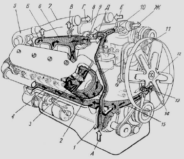
Fig. 17. Diagram of the cooling system of the diesel engine YaMZ-238
1 - water pump; 2 - the cavity of the cartridge cooling unit; 3 - water cavity in the head of the block; 4 - longitudinal water channel; 5 - turbocharger; 6 - right water pipe; 7 - connecting pipe; 8 - inlet pipe; 9 - thermostat; 10 - tee with connecting tubes; 11 - bypass pipe; 12 - a stub; 13 - inlet pipe of a liquid-oil heat exchanger; 14 - fan; 15 - transverse water channel; A - supply
coolant from a water radiator; B - to the cabin heater; B - air release; G - charge air supply to the air-to-air cooler; D, F - to the radiator; E - from air-to-air charge air cooler to cylinders
In addition, the YaMZ-238 diesel cooling system includes a water radiator, an air-to-air charge air cooler, and a remote thermometer mounted on a car.
During operation of the YaMZ-238 diesel engine, the circulation of the coolant in the cooling system is created by a centrifugal pump.
From the water pump of the YaMZ-238 engine of the Maz, Kraz, Ural cars, K-700 tractor (1), the fluid enters the transverse channel 15 and then through the right longitudinal channel 4 into the water cavity of the right row of cylinders, and into the left row of cylinders through the inlet pipe liquid-oil heat exchanger 13, cooling the oil in two elements, then into the left longitudinal channel.
In order for the coolant to pass through the liquid-oil heat exchanger, a plug 12 is pressed into the front cover of the distribution gears.
Next, the cooling fluid from the water cavities of the cylinders through the guide channels enters the cylinder heads to the most heated surfaces - exhaust channels and nozzle glasses and then collects in the drainage pipes 6.
When heating a cold YaMZ-238 engine, the channels connecting the drainage pipes to the radiator are blocked by thermostat valves 9.
Coolant circulates through a tee with connecting tubes 10 and a bypass pipe 11 to the water pump, bypassing the radiator, which accelerates engine heating.
Upon reaching a temperature of 80 ° C in the YaMZ-238 internal combustion engine water cooling system, the thermostat valves open, the heated liquid enters the water radiator, where it gives off heat to the air flow generated by fan 14, and then goes back to the water pump.
When the temperature of the coolant drops, thermostats automatically direct its entire flow directly to the water pump, bypassing the radiator.
Thus, by means of thermostats, the optimal thermal mode of operation of the YaMZ-238 engine is ensured.
Water pump of the YaMZ-238 diesel engine
The water pump (pomp) of the YaMZ-238 internal combustion engine of the centrifugal type is mounted on the front wall of the cylinder block and is driven by a V-belt from a pulley mounted on the front end of the crankshaft.
The design of the YaMZ-238 diesel pump for the Maz, Kraz, Ural vehicles, and the K-700 tractor is shown in Figure 18.
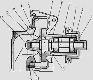
Fig. 18. Water pump (pomp) of the YaMZ-238 diesel engine
1 - drive pulley; 2 - a lock ring; 3 - bearings; 4 - roller; 5 - water spreader; 6 - mechanical seal; 7 - pump housing; 8 - a sealing ring; 9 - pipe of the water pump; 10 - impeller; 11 - impeller cap; 12 - a sealing ring; 13 - a sleeve of a sealing ring; A - mechanical seal; B - drainage hole
In the cast-iron housing 7 of the pump, the impeller 10 pressed onto the roller 4 rotates, creating a flow of coolant.
The roller of the YaMZ-238 water pump is mounted on two ball bearings 3 with one-sided sealing.
When assembling the pump, the bearing cavity is filled with Litol grease for the entire life of the pump without additional lubrication.
The seal of the bearing cavity of the YaMZ-238 pump is carried out by a self-clamping mechanical seal.
To monitor the tightness of the mechanical seal in the pump housing there is a drainage hole "B".
Drive pulley 1 is pressed onto the pump roller.
The water pump of the YaMZ-238 diesel engine is marked on the housing 236-1307010-B1.
The YaMZ-238 diesel engines of the Maz, Kraz, Ural and K700 tractors are equipped with a friction fan drive designed to turn the fan on and off depending on operating conditions.
21. The operation of the YaMZ-238 cooling system
See answer to question 20.
22. Coolants. Safety requirements when handling them.
Antifreeze:
1. grade 65 - mild orange liquid with a specific gravity at 20 ° C equal to 1,085-1,090, has a freezing point not higher than -65 ° C;
2. grade 40 - slightly mild yellowish liquid with a specific gravity at 20 ° C equal to 1.0675 -1.0725, has a freezing point not higher than -40 ° C;
Safety requirements:
1.1. Work with antifreeze is allowed to workers who have no medical contraindications, who have been instructed in labor protection and are trained in safe practices when working with coolants, safety measures for their transportation, receipt, storage, delivery and use.
1.2. Antifreeze contains ethylene glycol (EG), which has toxic properties. According to the degree of human exposure, they belong to the third hazard class, i.e. to substances moderately hazardous. Ethylene glycol can enter the body through the skin. The maximum permissible concentration (MPC) of antifreeze in the air of the working area is 5 mg / m³ for ethylene glycol. Due to the low volatility of ethylene glycol, antifreeze and auto-fluids do not pose a risk of inhalation poisoning. Therefore, when working with them, special measures to protect the respiratory tract, as a rule, are not required. Coolants do not possess cumulative (accumulation) properties. The most dangerous, if you drink ethylene glycol, the lethal dose is from 35 cm³ (depending on the weight of the person), in antifreezes (ethylene glycol solutions with water) - depending on the concentration - on average, the lethal dose is 50-100 g.
1.3. In order to exclude the possibility of using antifreeze for other purposes, the management of the organization or unit shall appoint a person responsible for the procedure for its storage, transportation and expenditure.
1.4. Antifreeze should be stored in a closed, dry, unheated room in a special container (factory, in serviceable metal hermetically sealed cans and barrels with screw caps). During transportation and during storage, all drain, bulk and air openings in the container must be sealed. Empty containers must also be sealed.
1.5. On the container in which the antifreeze is stored (transported), and on the empty container from under it should be indelible inscription in capital letters "POISON", as well as the sign "Danger. Poisonous substances".
1.6. Keep antifreeze away from open flames.
1.7. Antifreeze is poured into the container no more than 90% of its capacity.
1.8. Draining and loading processes from large tanks should be carried out using pumps, siphons.
a) to allow untrained persons to work with antifreeze;
b) release antifreeze into containers that do not meet the above requirements;
c) pour antifreeze through the hose by suction by mouth;
d) use antifreeze containers for transportation and storage of food products;
f) to drain antifreeze on the earth or in the sewerage
23. The device of the steering gear KrAZ - 255
The steering mechanism consists of a screw and a ball-nut-rack, which is constantly engaged with the gear sector. These parts are placed in a common housing, which is closed by covers. In the upper part of the crankcase there is an opening for filling and monitoring the oil level, and in the lower part there is a drain; both holes are closed with conical plugs
The steering screw rotates in two angular contact spherical bearings, one of which (upper) is pressed into the crankcase, and the other into the cover. When properly adjusted, these bearings must be preloaded.
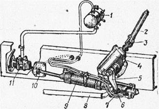
Fig. 25. Steering:
1 - an oil tank; 2 - a steering shaft; 3 - a cardan of a steering; 4 - steering gear; 5 - bipod; 6 - a hose of a drain highway; 7 - a hose of a discharge highway; 8 - longitudinal steering draft; 9 - power steering; 10 - power steering bracket; 11 - pump.
The screw and nut rail are selected from parts of the same size group. The semicircular threaded grooves on the screw and nut rail form a spiral channel that is filled during assembly with high precision balls. The balls included in the screw assembly assembly differ in diameter by no more than 2 microns. Violating the completeness of these parts is not allowed. High precision manufacturing of parts and their selection during assembly provide easy and smooth rotation of the screw in the nut rail.

Fig. 26. Steering gear:
1 - sector; 2 - sector shaft seal; 3 - needle shaft bearings of the sector; 4 - side cover of the crankcase; g - lock nut of the adjusting screw; 6 - adjusting screw; 7 - drain plug; 8 - an adjusting nut; 9 - a lock plate; 10 - a bolt of fastening of a lock plate; 11 - a pin of an adjusting nut; 12 - bottom cover; 13 - a sealing ring of a washer; 14 - washer of the bottom cover; 15 - screw bearings; 16 - a case of the steering mechanism; 17 - screw; 18 - filler plug; 19 - oil seal "inta; 20 - nut rail.
To obtain two continuous flows of rolling balls during rotation of the screw and to prevent the balls from falling out into the holes of the nut-rail, guides are inserted consisting of two stamped halves that form a closed system for rolling balls. The guides are secured to the rail using a clamp and screws.
The gear sector is made together with the shaft and installed in three needle bearings. The sector has five teeth. The middle tooth of the sector enters the middle cavity of the rack nut. At the end of the splined end of the sector shaft, a mark is applied for proper installation of the bipod. The marks on the bipod and the end of the sector shaft during assembly must be aligned. The axial position of the sector shaft is determined by the adjusting screw, the spherical head of which is located in a special sector bore.
When the bipod is disconnected, the steering wheel should not be turned all the way to the extreme positions, as this can lead to damage to the guides in the nut-rail. The full angle of rotation of the bipod corresponds to five turns of the steering wheel.
24. The device of the steering column with a shaft and a steering wheel KrAZ - 255
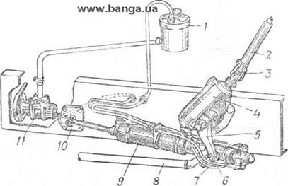
Fig. 30. Steering:
1 - an oil tank; 2 - steering column shaft: 3 - cardan joint; 4 - steering gear; 5 - steering bipod; 6 - pipeline drain line; 7 - discharge pipeline; 8 - longitudinal steering draft; 9 - power steering; 10 - amplifier bracket; 11 - oil pump
The steering screw is connected to the steering column shaft via a universal joint. The connection of the amplifier with the steering mechanism is carried out through the bipod, which is attached at one end to the splined end of the sector shaft, and the second (lower) is connected to the ball pin of the distributor.
The steering column is strengthened using a bracket cast from malleable cast iron KCH35-10 with a cover on a stamped cab amplifier.
The steering wheel is pressed against the conical neck of the shaft (taper 1: 15) with a nut with M27X1 thread and fixed with a segment key. The universal joint fork is also fixed to the steering shaft with a segment key and a coupling bolt.
25. Rechargeable batteries, their marking and characteristic. Bringing the battery into working condition. Charging the battery. Battery Care The procedure for removing the battery from the machine and installing the battery on the machine.
Rechargeable battery (battery) It is a chemical current source that stores the energy needed to power an electric starter that rotates the engine during start-up. In addition, it ensures the operation of electrical devices of the car with a lack or absence of the power developed by the generator.

Serving battery device:
1 - case;
2 - negative electrode (plate);
3 - separator;
4 - positive electrode (plate);
5 - a platelet;
6 - reference prisms;
7 - a cover;
8 - filler plug;
9 - a positive conclusion;
10 - interelement jumper (connecting bridge);
11 - negative conclusion
Battery Marking:

According to GOST 959-2002 on each battery should be applied:
- trademark or name of the manufacturer;
- symbol batteries (fig.); - polarity signs: plus “+” and minus “-”;
- production date - month, year;
- number of ND (normative document) for this battery;
- rated capacity in ampere-hours (A.h);
- rated voltage in volts (V);
- cold scroll current in amperes (A);
- the mass of the battery (if it is 10 kg or more);
- safety signs;
- a symbol of recycling.
The electrical system of the KrAZ - 255B1 automobile is single-wire, with a negative pole connected to the negative pole of current sources and consumers. Sources of electricity are two rechargeable batteries 6CT - 182EM, connected in series with each other, and a generator G - 288E, working in conjunction with a voltage regulator. The capacity of the battery is 6ST - 182EM 655 kCl (182 Ah) at a 20-hour discharge mode.
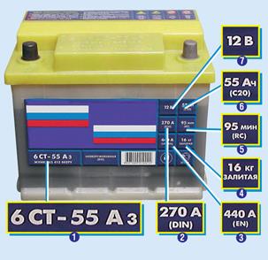
Marking of the Russian battery:
1 - reference designation;
2 and 3 - cold scroll current according to DIN and EN;
4 - weight;
5 - reserve capacity;
6 - rated capacity;
7 - rated voltage
Battery Charging:
Batteries are produced by factories in dry-charged version. To bring them in
working condition, prepare the electrolyte of the appropriate density, fill it in the batteries and, if necessary, recharge the batteries after soaking the plates. Preparation of electrolyte, pouring it into batteries and battery charge should
made in accordance with the instructions for
battery operation. From quality
bringing the batteries into operation depends
reliability of their further operation.
Battery charge. Charge rechargeable batteries from a direct current source when operating them, as well as during
operation and storage. The positive terminal of the battery is connected to the positive pole of the current source, and the negative to negative.
Set the charge current and
in the future, keep the rheostat at the same level or by changing the voltage of the charging source, depending on the charger used.
Battery Care:
the main points that should be observed with proper care of the battery:
- always check the strength of the battery mount, move it by hand with the engine turned off;
- in order to get rid of oxidation at the places of terminal closure with battery tips, you can use anti-corrosion agents;
–If the voltage is less than declared, be sure to charge;
- for prolonged non-use of a car, bring the battery home, or at least disconnect the negative terminal from the battery;
- Always monitor the cleanliness of the openings in the covers, they are necessary to remove gases from the battery.
The procedure for removing the battery from the machine and installing the battery on the machine:
1. Open the hood on the car.
2. Loosen the nut of the handpiece bolt ...
3. ... and remove the wire from the negative terminal of the battery.
4. Set aside the rubber protective cover of the plus terminal ...
5. ... loosen the nut of the coupling bolt of the handpiece ...
6. ... and disconnect the wire from the plus terminal of the battery.
7. Release the socket wrench to tighten the nut securing the battery bracket.
8. Turn away nuts of fastening of a level to couplers of the storage battery ...
9. ... and remove the mounting bracket and ties by turning them 45 °.
10. After finally unscrewing the nut, remove the battery mounting bracket ...
11. ... and then remove the battery itself from the vehicle.
12. Install the battery on the vehicle in the reverse order to removal. Before connecting the wires, strip the battery terminals and the inner surfaces of the wire ends with fine-grained sandpaper. Connect the wires in the reverse order to removal, observing the polarity. After connecting the wires to the terminals, apply a thin layer of Litol-24 grease or similar on the wire terminals and exposed surfaces of the terminals (copper-based conductive greases are most preferred).
30. Purpose and general device of the KrAZ 255 transmission
The clutch is double-disc, with peripheral springs, the shutdown drive is mechanical. Gearbox - 5-speed, with synchronizers in II, III, IV and V gears. Transfer case - 2-speed, with a center differential lockable middle and rear axles. Control of the transfer case - three levers. The driveline consists of five shafts: gearbox - transfer case, transfer case - front axle, transfer case - middle axle, transfer case - rear axle (two shafts with intermediate support). The main transmission of the drive axles is double with bevel helical and spur gears.
32. purpose, device and operation of the clutch Kraz-255.
The car has a dry friction-type double-disc clutch with cylindrical pressure springs located on the periphery. For normal operation of the clutch, it is necessary that there is a gap of 3.2-4.0 mm between the thrust ring of the pull levers and the release bearing with the clutch engaged. This clearance corresponds to a free travel of the clutch pedal, equal to 32-40 mm (full pedal stroke 165-175 mm). The lack of pedal free play causes slipping of the clutch, which leads to intensive wear of the friction linings of the driven discs, their warping, as well as the failure of the release bearing. Clutch adjustment. The clutch is regulated in two stages: first, the amount of departure of the middle drive disk is adjusted to provide the necessary gaps between the clutch working surfaces when it is turned off, and then the clutch pedal moves freely.
33. purpose, device and operation of the gearbox Kraz-255
The gearbox is five-speed, has five gears for moving forward and one reverse. Two inertial synchronizers are used to activate the second - third and fourth - fifth gears.
26. Generator
Appointment and device of the generator. The generator is designed for parallel operation with batteries and serves as a source of electricity in the car.
The G-271 generator (Fig. 57) is a three-phase synchronous electric machine of alternating current of electromagnetic excitation with a built-in rectifier unit VBG-1.
Rated voltage, V .............................................. ........................... 24
Memorial power, W .............................................. ........................... 500
Rated rectified current, A ............................................. ........... 20
Self-limiting current at 5000 rpm, A ......................................... ........ 30 + 5
The initial frequency of rotation of the excitation, at which the generator develops a voltage of 25 V (at a temperature of the generator and the environment + 20 ° C and independent excitation), rpm (not more):
with a load current equal to zero ............................................ ............. 1050
with a load current of 20 A ........................................... ................ 2100
Excitation current, L (no more) .......................................... ........................... 1,2
The pressure value of the brush springs, gf .............................. 180 ... 260
The generator consists of a stator, a rotor, two covers, a fan and a pulley.
Stator 4 is composed of electrical steel plates. The inner part of the stator has 18 grooves evenly spaced around the circumference, in which the winding is placed. The stator winding is three-phase, connected according to the "star" scheme (in each phase there are six continuously wound coils).
The rotor consists of an excitation coil wound directly on a steel sleeve, to the ends of which are adjacent two beak-shaped poles 6, forming a twelve-pole magnetic system. The sleeve and the beak-shaped poles are fixed to the shaft 5 by means of a press fit on the knurling. Contact rings 7 are also pressed onto the rotor shaft, to which the ends of the field winding are soldered.
The cover 8 on the side of the contact rings (back cover) has ventilation windows and a tide (paw), which serves as a bracket for mounting the generator. A brush holder (brush assembly 9) is mounted on the lid, in the guide holes of which there are two brushes of rectangular cross section, and a rectifying unit is located inside it. Conclusions "-b", "W" and "-" on the lid are used for connection:
“+” - to the “+” terminal of the relay-regulator;
“Ш” - to the “Ш” terminal of the relay-regulator;
"-" - to the screw of "mass" of the relay regulator designated by the letter M.
The cover 3 on the drive side also has ventilation windows and two tides (legs), one of which is used to fasten the generator to the engine bracket, and the other (with a threaded hole) is used to fasten to the tension bar, with which the belt tension is regulated. There are two threaded holes in the cover for removing it from the rotor shaft when disassembling the generator.
The rotor shaft of the generator rotates in two ball bearings of closed type (with double-sided sealing) installed in the front and rear covers. During assembly, these bearings are lubricated with No. 158 grease, which does not require replacement during operation.
The generator is cooled by the air flow from the fan 2, mounted on the rotor shaft from the drive side, through the ventilation windows in the covers.
The generator operates as follows. The field winding, powered by direct current, creates a magnetic flux around the rotor. When the rotor rotates, the magnetic flux changes in magnitude and direction, as a result of which a variable EMF is induced in the stator winding. The alternating current generated by the generator is converted to a constant rectifier unit mounted in the cover on the side of the slip rings. The constant voltage of the generator is supported by a relay controller.
Adjustment of a tension of a belt of a drive of the generator. To adjust the belt tension, it is necessary to loosen the bolts securing the front and rear legs of the generator to the bracket and the bolt securing the generator to the tension bar. By hand or lever, tilt the generator to the side of the belt tension to the required value, then tighten the bolts securely. At the end of the adjustment, check the belt tension. A correctly tensioned belt when pressed in the middle of its branch with a force of 3 kgf should have a deflection of 10 ... 15 mm. Too much belt tension will lead to increased loads on the bearings of the generator and their premature failure.
The axis of the streams of the alternator pulley and the drive pulley must be in the same plane. The coincidence of the axes is provided by moving the bracket of the generator.
Control check of the generator. During operation (in the event of a forced replacement of the stator, rotor, windings and other details), it is necessary to check the start frequency of the generator excitation rotation for its compliance technical specification. Testing is performed on a bench (from a direct current source), which allows changing the rotation frequency of the generator rotor from 0 to 5000 rpm. The connection diagram of the generator and devices for testing is shown in Fig. 58.
When checking the generator, increase the rotational speed of its rotor smoothly so that the voltage of the generator does not exceed 25 V.
Dismantling and assembling the generator. The generator must be disassembled in the following sequence:
1. Remove the screws that secure the brush holder to the cover and remove the brush holder.
2. Loosen the screws securing the ball bearing cover.
3. Unscrew the coupling screws securing the generator covers.
4. Remove the cover on the side of the slip rings together with the stator (if necessary, remove the cover with a puller).
5. Disconnect the phase leads of the stator winding from the leads of the rectifier block.
6. To turn off a nut of fastening of a pulley, previously having clamped a rotor in a vice for one of poles or holding it with a wrench.
7. Remove the pulley, fan, knock out the key and remove the thrust bush.
8. Remove the cover together with the ball bearing from the rotor shaft (on the drive side) using a puller, using the screw holes on the cover for this purpose.
The generator must be assembled in the reverse order of disassembly.
Before installing the rectifier unit, it is necessary to check the serviceability of all its monoblocks. Testing should be carried out with a direct current voltage of 12-24 V according to the circuit shown in Fig. 59.
P - / 2-transition is working if the control lamp 3 lights up in position / and goes out in position II. When the p- / r-junction is broken, the lamp burns in both positions, when the p-p-junction breaks, the lamp does not burn in both positions. It is not allowed to check p - // - transitions with voltage of the AC mains.