Purpose and general design of the engine cshm. Crank mechanism (KShM)
Creep (Fig. 32) - a link in the crank mechanism, which can make a complete revolution around a fixed axis. The crank (I) has a cylindrical protrusion - spike 1, the axis of which is offset relative to the axis of rotation of the crank by a distance r, which can be constant or adjustable. A more complex rotating link of the crank mechanism is the crankshaft. Eccentric (III) - a disk mounted on a shaft with an eccentricity, that is, with an offset of the axis of the disk relative to the axis of the shaft. An eccentric can be considered as a constructive type of crank with a small radius.
Fig. 32
Crank mechanism - a mechanism that converts one type of movement into another. For example, uniformly rotational - into translational, oscillatory, non-uniform rotational, etc. The rotating link of the crank mechanism, made in the form of a crank or crankshaft, is connected to the strut and another link by rotational kinematic pairs (hinges). It is customary to distinguish between such mechanisms on the crank, crank, rocker, crank, etc., depending on the nature of the movement and the name of the link in conjunction with which the crank works.
Are used crank mechanisms in piston engines, pumps, compressors, presses, in the drive of movement of metal-cutting machines and other machines.
crank mechanism - One of the most common mechanisms for converting motion. It is used both for converting rotational motion into reciprocating (for example, piston pumps), and for converting reciprocating into rotational (for example, internal combustion engines).
Connecting rod - a part of the crank (slider) mechanism that transfers the movement of the piston or slider to the crank of the crankshaft. The part of the connecting rod used to connect to the crankshaft is called the crank head, and the opposite part is called the piston (or slider) head.
The mechanism consists of a stand 1 (Fig. 33), a crank 2, a connecting rod 3 and a slider 4. The crank performs continuous rotation, the slider performs a reciprocating movement, and the connecting rod carries out a complex, plane-parallel movement. , The full stroke of the slider is equal to twice the length of the crank. Considering the movement of the slider from one position to another, it is easy to see that when the crank is turned at equal angles, the slider travels a different distance: when moving from the extreme position to the middle, the sections of the slider path increase, and when moving from the middle position to the extreme, they decrease. This indicates that with a uniform movement of the crank, the slider moves unevenly. So the speed of the slider moves from zero at the beginning of its movement and reaches its maximum value when the crank and connecting rod form a right angle between themselves, then again decreases to zero at another extreme position.
Fig. 33
The unevenness of the slider's movement causes the appearance of inertia forces that have a negative effect on the entire mechanism. This is the main drawback of the crank-slide mechanism.
In some crank mechanisms, there is a need to ensure the linearity of movement of the piston rod 4 (Fig. 34). To do this, between the crank 1, connecting rod 2 and the slider 5, use the so-called crosshead 3, which takes on the swinging motion of the connecting rod (4 - intermediate rod).
Fig. 34
Moving parts:
- piston assembly with piston rings and piston pin.
- connecting rod.
- crankshaft.
- flywheel.
The piston made of aluminum alloy has a bottom, a sealing part and a guide part. The bottom and the sealing part make up the piston head. Grooves are grooved in the piston head for piston rings, in the middle part of the piston (sealing) there are boss tides with holes for installing the piston pin. In the lower part (guide) of the skirt, cutouts are made for the passage of the counterweights of the crankshaft during engine operation. Cutouts reduce piston mass.
Due to the large heating, the diameter of the piston head is made smaller than the diameter of the piston guide part (skirt).
Jamming of the piston during heating is eliminated by giving the piston skirt an oval shape, the small axis of the oval coincides with the longitudinal axis of the piston pin, and the major axis is perpendicular to it. When heated, the piston expands more in the direction of the small axis of the oval, coinciding with the longitudinal axis of the piston pin, where the bosses have the largest mass of metal and take a cylindrical shape. The piston skirt has a U or T-shaped slot, which gives it a springy property and ensures the operation of an unheated engine without knocking. For VAZ and UAZ engines, for the piston to work in an unheated state without knocking, a steel thermostatic ring is embedded in the piston body. To improve the running-in of the pistons to the cylinder liners and protect them from scoring, the piston skirt is covered with a thin layer of tin. The piston pin hole is offset 1.5 mm to the right in the direction of travel. This reduces the distortion and knocking of the piston when it passes through the BMT
Piston rings are divided into compression and oil scraper. Compression rings seal the piston in the cylinder liner. To increase wear resistance, the surface of the upper piston ring is chrome plated. When accelerating, the second ring is covered with a tin layer. oil scraper rings are removed from excess oil from the walls of the liners and prevent oil from entering the combustion chamber. Rings are made of cast iron or steel. Oil scraper cast-iron ring differs from compression through-cuts for oil passage. In the piston groove for the oil scraper ring, holes were drilled to divert the oil into the piston. The piston pin is used to swivel the piston with the upper connecting rod head. The fingers are made hollow of steel. Their outer surface is hardened by high frequency currents to increase wear resistance. The most common "floating" fingers that rotate freely in the bushing of the upper connecting rod head and piston bosses. From the axial section (displacement), the piston pin is fixed by retaining rings inserted into the undercut of both piston bosses. The connecting rod transfers force from the piston to the crankshaft. It consists of an upper head, a rod and a detachable lower head, fixed to the crank pin of the crankshaft. The connecting rod and its cover are made of steel. The connecting rod rod has an I-section and can withstand significant, variable in magnitude and direction of load. A sleeve of tin bronze is pressed into the upper head of the connecting rod. At the top of the connecting rod head there is a hole for lubricating the piston pin. Thin-walled steel liners are inserted into the lower head of the connecting rod. The lower head and cover are connected by two bolts.
Bearing shells are made of steel tape. their inner surface is poured with a thin layer of antifriction tin-aluminum alloy. The liners from turning in the lower head of the connecting rod and axial movements are held by the bent tendrils, which are extruded at the joints and abut in the corresponding grooves in the connecting rod and its cover.
The crankshaft senses the forces transmitted from the pistons by the connecting rods and converts them into torque. It has root and connecting rod necks connecting the root and connecting rod necks, counterweights, a flange for attaching the flywheel, a sock on which the crank of the starting handle, the distribution gear and the fan drive pulley and the water pump are mounted. The connecting rod neck with cheeks forms a knee, or crank.
The crankshafts of the VAZ, GAZ, UAZ engines are cast from magnesium cast iron, and the crankshafts of the Moskvich automobile are steel. The crankshaft necks are carefully ground and polished, and also quenched with high-frequency currents. The number of connecting rod journals is equal to the number of cylinders. For uniform alternation of working strokes, the knee of the shaft of the four-cylinder engine, if you look at the shaft from the end, are located at an angle of 180, i.e. the first and fourth knees are directed in the same direction. The second and third in the opposite. Indigenous necks-5. The crankshaft rotational speed reaches 4000-6000 rpm, therefore, there are large centrifugal forces acting on the connecting rod journals, cheeks and lower connecting rod heads. These forces load the main bearings, causing their accelerated wear. To unload the main bearings from centrifugal forces, counterweights located on the extension of the cheeks of the crankshaft are used.
The main and connecting rod journals of the crankshaft are connected by inclined channels (in the cheeks) for supplying oil from the main bearings to the connecting rod bearings. Hollow connecting rods have cavities - dirt traps. In these cavities, under the action of centrifugal forces, heavy particles and wear products of parts contained in oil are deposited during engine operation. Dirt traps are cleaned when disassembling the engine, turning off the plugs. Axial loads of the crankshaft are perceived by a persistent steel washer and steel washers filled on one side with washers and located on both sides of the front main bearing.
The main and connecting rod bearings have the same design. The upper liners are installed in a recess (bed) of the upper part of the crankcase. The lower ones are in the cover of the main bearings. The liners have oil grooves and holes. To prevent oil leakage from the crankcase at the front and rear ends of the crankshaft, oil deflectors and oil seals are installed.
The flywheel increases the uniformity of rotation of the crankshaft at a low frequency and transmits the transmission torque of the car. A flywheel is made of cast iron. A steel gear ring is pressed onto the flywheel rim, designed to rotate the crankshaft with a starter when starting the engine. The clutch mechanism is attached to the flywheel.
Fixed parts:
- Cylinder block.
- Cylinder head.
The cylinder block is cast from cast iron (VAZ) or aluminum alloy (ZMZ) - Zavolzhsky Motor Plant, (UAZ) - Ulyanovsk Automobile Plant. In the casting of the cylinder block, walls, cooling jackets are made. The cylinders serve as guides for the pistons, and a duty cycle is performed in them.
To increase the wear resistance of the cylinders and to simplify the repair and assembly, the sleeves of gray cast iron are pressed into the block (ZMZ, UAZ, and Moskvich). Reducing wear of the upper part of the sleeves is achieved by installing acid-resistant cast iron inserts in them. At the bottom, the liner is sealed with a soft red copper gasket, and at the top, the cylinder head gasket. The inner surface of the sleeve is carefully treated and called a mirror. In the casting of the cylinder block, beds are provided for the main bearings of the crankshaft, bearing-distribution. shaft and space for mounting various components and devices.
The sump or bottom of the crankcase protects the crankcase from dust or dirt and serves as a reservoir for oil. It is stamped from sheet steel. To the upper part of the crankcase, the pallet is bolted, the seal is achieved by cork gasket. The plane of the crankcase connector is usually located below the axis of the crankshaft and increases the rigidity of the crankcase.
The cylinder head is cast from an aluminum alloy. In the head there are combustion chambers, there are threaded holes for spark plugs, intake and exhaust valves, pressed seats and valve guides. The cylinder head has a cooling jacket communicating with the cooling jacket of the cylinder block. The tightness of the connection of the head with the cylinder block is ensured by a metal-asbestos gasket. The cylinder head is covered with a stamped cover from above. A gasket is installed between the cap and cylinder head.
Part 5
Engine mount.
Car GAZ-24 (Volga): The engine is mounted on a short frame welded to the base of the body. Attachment points - three. Two on either or sides of the front of the engine. One under the gearbox extension. Gas distribution. mechanism (timing) when the camshaft rotates, the force from the cams is transmitted to the pushers, rods, rocker arms and valves.
Timing Parts:
- Camshaft.
- Pushers.
- Rods.
- Rocker.
- Valves
- Distribution gears.
The camshaft provides timely opening and closing of valves. They make it from steel or cast iron. The shaft of a four-cylinder engine has five support necks for simplification of installation of a shaft in the block of cylinders the diameter of necks subsequently decreases, starting from a forward neck. The bushings of the support journals are made of steel, and the inner surface is covered with a layer of lead babbitt. On the camshaft, there are cams and gears of the oil pump drive and the ignition interrupter-distributor, an eccentric, the fuel pump drive, two cams on the camshaft for each cylinder. The camshaft receives rotation from the crankshaft in four-stroke engines, the duty cycle occurs in two revolutions of the crankshaft. During this period, the intake and exhaust valves of each cylinder should open once, and the camshaft must rotate one revolution \u003d camshaft. the shaft should rotate 2 times slower than the crankshaft. Therefore gear distribution. the shaft has 2 times more teeth than the crankshaft gear.
The crankshaft gear is steel, and the camshaft gear is textolite. To reduce noise and give smooth operation, the teeth of both gears are made oblique.
Pushers are designed to transmit power from the cam cam. They are made of steel. The ends of the pushers in contact with the cams to reduce wear make spherical and weld bleached cast iron. The pushers move in the guide holes. cylinder blocks. Inside the pusher there are spherical recesses for installing the rods. The rods transmit force from the pushers to the rocker arms. They are made of duralumin rod, and steel tips are pressed onto the ends. On one side, the bar abuts against the pusher. On the other hand, into the spherical surface of the adjusting screw screwed into the beam.
The rocker transfers force from the bar to the valve. A rocker is made of steel or cast iron. The arms of the rocker arm are not the same - the shoulder on the valve side is longer. This reduces the lifting height of the pusher and the rod. A screw is screwed into the short arm of the rocker arm to adjust the thermal clearance. The rocker arms are mounted on a common axis, mounted in the cylinder head on the uprights. The axis of the rocker arm is hollow. Rockers swing on tin bronze bushings.
Valves (8) - open and close the inlet and outlet channels. The valve consists of a plate-shaped flat head and a stem. To improve the filling of the cylinders with a gasoline-air mixture, the diameter of the head of the inlet valve is made larger than the outlet. Made from alloy steels. Valve seats are made plug-in to simplify replacement. The material for the saddles is heat-resistant cast iron. Saddles are pressed into the undercut of the cylinder heads. The working surface of the valve (chamfer) has an angle of 45 *. She carefully rubbed to the saddles. The valve stem has a recess in which crackers are inserted to secure the thrust washer of the valve spring.
Crackers tightly covers the conical sleeve. The lower end of the spring rests on the washer. An oil reflector cap made of oil-resistant rubber is installed on the intake valve stem. This prevents oil leakage through the gap between the guide sleeve and the intake valve stem. To tightly close the valve, there is a gap between its stem and rocker nose. If the clearance is less than the specified size, the valve is loose. As a result, gas leakage and burning of the valve working surface occurs. If the clearance is larger than the specified size, the valve opening is incomplete. The filling and cleaning of the cylinders is insufficient, the shock load on the mating parts of the valve mechanism is increased, leading to accelerated wear. For engines installed on ZMZ UAZ, the gap between the valve stem and the toe of the rocker arm on a cold engine should be for the first and eighth valves 0.3-0.35. For the rest, 0.35-0.40. For GAZ31-02, this gap should be equal to 0.4-0.45mm, and between the add. valve and rocker-0.2mm.
The order of the engine cylinders: Volga
1-1
2-2
3-4
4-3
for Moskvich-1,3,4,2.
The diesel crank mechanism converts the reciprocating motion of the piston into the rotational motion of the crankshaft. The main details of the crank mechanism of the YaMZ-240B diesel engine: cylinder liners, pistons with piston fingers and rings, connecting rods and crankshaft with bearings, flywheel.
The cylinder liner is made of alloy cast iron. Its inner surface (mirror) is hardened. The sleeve has a support flange and two guide belts. Two sealing rings and one anti-cavitation ring are installed in the grooves of the lower belt. The sleeve is pressed into the crankcase until it stops with the upper flange in the ring groove of the block. The cylinder liners are called wet due to the presence between the liners and the block of the cavity for access of coolant.
The piston is made of high silicon aluminum alloy. An ω-shaped groove is made in its head, which serves as a combustion chamber. The piston has two internal bosses with holes for the piston pin and five annular grooves to accommodate three compression rings and two oil scraper rings. To prevent the piston from jamming in the cylinder during heating, the diesel engine is assembled so that between the piston and the cylinder there is a gap of 0.19 ... 0.21 mm. The accuracy of the landing is ensured by the selection of jointly working pistons and sleeves of one of the six size groups (Table 3). Marking of dimensional groups is applied on the piston bottom and on the upper end of the sleeve.
A piston pin connects the piston to the connecting rod. It can move along the axis of the bosses and is therefore classified as floating. The movement of the piston is limited by lock washers installed in the recesses of the bosses.
Compression rings have a trapezoidal section. The outer surface of the upper ring is covered with a layer of porous chromium. Oil scraper rings - box section with expanders.
The connecting rod is made of steel of I-section. He has two heads. A bronze bushing is pressed into the upper head, to which oil is supplied from the lower head by axial drilling in the connecting rod shaft. The lower head has a connector at an angle of 55 ° to the axis of the rod, which allows you to install and remove the shaft-piston kit through the cylinder. The caps of the lower heads are processed in assembly with the connecting rods, so they are not interchangeable. Marks on paired parts in the form of the same conditional numbers and risks are applied to both parts of the connecting rod near one of the joints. At the junction of the connecting rod with the cover, triangular teeth are made that prevent the radial shift of the cover relative to the connecting rod. In the axial direction, the cover is fixed with a pin, which is pressed into the connecting rod and enters the groove of the cover. Replaceable thin-walled liners are installed in the lower head of the connecting rod, the base of which is made of steel, and the working layer is made of lead bronze. Upper and lower liners are interchangeable.
The crankshafts of YaMZ diesels are made by stamping from steel. The shaft necks are hardened by high frequency currents. In the cheeks of the shaft, channels for supplying oil to the cavities in the connecting rod journals were drilled. In these cavities (they are closed with plugs), the oil is subjected to additional centrifugal cleaning.
The crankshaft of the YaMZ-240B diesel engine has seven main bearings and six connecting rod journals. The cranks of the shaft are located in three planes at an angle of 120 ° to one another. A torsional vibration damper is installed at one end of the shaft, and a flywheel is at the other. On the supporting journals are made treadmills serving as inner rings for single row rolling bearings with short cylindrical rollers. The outer rings of the bearings are pressed into the bores of the crankcase. Their axial movements are limited by snap rings.
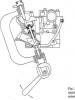
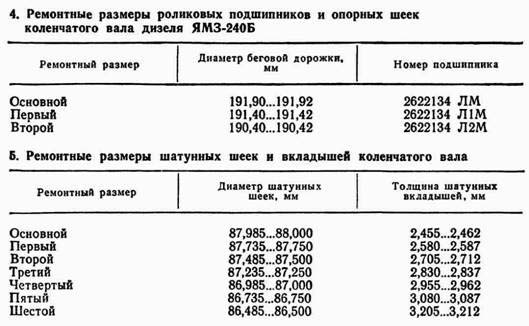
When the support and connecting rod journals wear, the shaft is polished to the next repair size, roller bearings (Table 4) and connecting rod bushings (Table 5) are replaced. In the axial direction, the crankshaft is fixed with two bronze rings 3 and 15 (Fig. 4) installed in the housing 10 of the thrust bearing. The latter is attached to the front end of the crankcase 11.
The torsional vibration damper is designed to reduce vibrations that occur when the frequency of the natural oscillations of the shaft coincides with the frequency of flashes in the cylinders. The absorber absorbs vibrational energy due to friction.

It consists of a housing 4, a bronze bushing 5, a hub 2 and a disk 8. The gaps between the disk and the housing are filled with a viscous polymethylsilane-oxane fluid. This liquid is charged through two holes, after which they are closed with stoppers and sealed. A faulty damper not only does not reduce torsional vibrations, but also creates a moment of inertia, additionally loading the shaft.
The drive mechanism (Fig. 5) of the following auxiliary units is installed in the bore of the front cover of the diesel case: a cooling system fan, a pneumatic system compressor, and an electrical equipment generator. In this mechanism, the torque from the toe of the crankshaft is transmitted to the hub 4 through the hub 17, the roller 3, the drive shaft 15 and the segment key 8. A V-belt drive pulley is attached to the hub 4. Lubricant to the splines of the connecting roller and to the bearings 11 and 14 enters through a calibrated hole A in the plug 18.

The crankshaft of the YaMZ-238NB diesel engine has five main bearings and four connecting rod journals. To balance the diesel engine and unload the main bearings from inertial forces, counterweights on the cheeks, as well as external masses on the flywheel and the front end of the shaft, are provided. In the axial direction, the shaft is fixed by four bronze half rings that are installed in the recesses of the rear main bearing journal and are locked with pins pressed into the cover of the rear main bearing. In the lower half rings grooves are made. The crankshaft is balanced complete with counterweights.
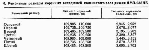
When the support journals wear, the shaft is resurfaced to the next repair size (Table 6). Worn connecting rods are restored in the same way as on the crankshaft of a YaMZ-240B diesel engine (see Table 5).
When regrinding the shaft necks, it is necessary to ensure a smooth transition radius (5.95 ... 6 mm) from the necks to the cheeks without undercuts, burns and rough scratches; the surface roughness Ra of the necks and transition radii should not exceed 0.32 μm. In order to avoid the formation of grinding cracks, reduce fatigue strength and imbalance in shaft balancing, it is forbidden to grind the connecting rod journals from 88 mm to 85 mm in diameter, and the main ones from 105 mm in diameter to 105 mm.
The flywheel is designed for uniform rotation of the crankshaft, the removal of pistons from the dead center and facilitate starting the engine. It is made of gray cast iron. The flywheel is bolted to a special hub mounted on the tapered shank of the crankshaft. The hub is fitted with a large interference fit, so you can remove and install it only with the help of a special device; heating the hub is not allowed. A gear ring is pressed onto the flywheel rim, which is necessary for starting the diesel engine with a starter and cranking the crankshaft manually.
The crankshaft of the YaMZ-240B diesel engine can also be turned with a special crowbar, which is inserted into one of the radial holes in the flywheel through the lower hatch of its crankcase. The crankshaft of the YaMZ-238NB diesel engine is turned with a key for the pulley mounting bolt or crowbar inserted into the flywheel holes.
Maintenance of the crank mechanism. When operating a YaMZ-240B diesel engine, periodic maintenance crank mechanism. On the YaMZ-238NB diesel engine, every 3000 moto-h, the condition of the piston rings and the connecting rod and main bearing shells is checked, current repairs are carried out.
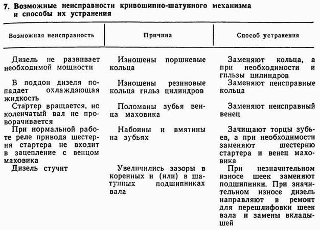
Maintenance of the crank mechanism. During operation, the following malfunctions of the crank mechanism may occur (Table 7), the elimination of which requires disassembly.
Piston rings are replaced when the cylinder head and the pan are removed in this order.
1. Clean the upper belt liner from soot so that it is easier to remove the piston.
2. Disconnect and remove the cover of the lower connecting rod head and remove the piston assembly with the connecting rod from the cylinder (up). If the piston must be disconnected from the connecting rod, then the retaining rings are removed from the piston bosses, heat the piston in an oil bath to 353K (80 ° C) and remove the piston pin.
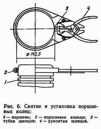
3. With special forceps (Fig. 6), restricting the extension of the ring to a holder with an inner diameter of 142.5 mm, remove the old piston rings.
4. Clean the piston from soot so as not to damage the end surfaces of the grooves.
5. Before assembly, thoroughly rinse and lubricate the parts with engine oil. The oil channels are purged with compressed air.
6. Connect the piston to the connecting rod. In this case, the piston pin must freely enter the heated piston. The piston is installed so that the combustion chamber in the piston is biased towards the fuel pump high pressure. The marks on the connecting rod and its cover should be the same, and the risks should be the same. The threads and bearing ends of the heads of the connecting rod cover bolts are lubricated with engine oil and tightened in two steps, starting with a long bolt (first with a torque of 100 Nm and then 200 ... 220 Nm).

Put the rings on the piston in the reverse order of removal. Compression rings are slanted and branded up to the piston head. Locks of adjacent piston rings are deployed in opposite directions in the plane of the piston pin.
A special mandrel is installed in the cylinder liner (Fig. 7) with a conical inner surface and a centering collar.
A connecting rod and piston set is placed in the cylinder, sequentially recessing the rings into the piston grooves and upsetting it first inside the mandrel and then inside the cylinder liner.
The rubber rings on the cylinder liners are replaced by removing the cylinder heads, connecting rod and piston sets and the pallet. Operations are performed in this sequence.
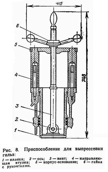
A device is introduced (Fig. 8) into the inner cavity of the sleeve and is hooked with a strap 1 to the lower end of the sleeve.
Put the device with guide bushings 4 on the studs of the crankcase.
The sleeve is pressed out of the block by rotating the nut 6 by the handles.
O-rings and anti-cavitation rings are removed from the cylinder liner.
Thoroughly clean the liner of corrosion and scale products and lubricate with a thin layer of motor oil.
Install sealing and anti-cavitation rings in the grooves of the sleeve, avoiding cuts, distortions, twisting and mechanical damage.
Place the sleeve assembly with the rings in the corresponding block bores.
Wipe with a cotton cloth and lubricated with engine oil cylinder liners and connecting rod journals.
Install the connecting rod and piston sets in the cylinder liners and bolts the connecting rod caps. Then check the total axial clearance between the ends of the lower heads of the connecting rods and the cheeks of the shaft (should be 0.15 ... 0.70 mm). It is necessary to measure the gap between the ends of the connecting rods, and not the covers. Lid protrusion beyond the end of the connecting rod. This defect is eliminated by loosening the bolts and sliding the covers with light blows of a rubber mallet. Further assembly of the diesel engine is carried out in the reverse order of disassembly.
The flywheel crown is replaced by first removing the air purification and exhaust systems, the hood lining, the fan and dust separator of the ventilation and heating systems of the cab, the gearbox shaft of the gearbox, the semi-rigid clutch and gearbox of the pump drive and the cover of the front hatch of the cab floor, and also disconnecting the fuel supply drive and electrical wires from TM100, TM103 sensors (installed in water pipes) and MM355 (installed in the turbocompressor housing on a YaMZ-238NB diesel engine). The flywheel crown is removed in this sequence.
1. Unbend the mustache of the locking plates of the flywheel bolts.
2. Turn out bolts of fastening of a flywheel to a nave.
Screw the two technological bolts Ml2 into the holes of the flywheel all the way to the end of the hub and remove the flywheel. (To avoid skewing the flywheel, the bolts must be screwed in at the same time.)
Unscrew the mounting bolts and compress the crown from the flywheel.
Then the flywheel is cleaned of contaminants and corrosion products, washed in diesel fuel, and then a new crown is pressed onto it, which is bolted. Assembly is carried out in the reverse order of disassembly.
The main and connecting rod bearings are replaced as follows. When replacing connecting rod bearings, the preheater boiler and the pan are removed first. To replace the main bearings, the crankshaft must also be removed. On the YaMZ-240B diesel engine, this is associated with the dismantling of the connecting rod and piston sets, as well as the mechanisms and parts mounted on the toe (auxiliary drive, torsional vibration damper, thrust bearing) and on the shank (flywheel, flywheel hub) of the crankshaft, and on the diesel YaMZ-238NB - with the same operations (with the exception of dismantling the torsional vibration damper) and additionally dismantling the front cover of the cylinder block and the flywheel housing. When replacing the bearings of the crankshafts, it must be ensured that the sizes of the bearings correspond to the sizes of the necks of the shafts (see Table 4-6). Main bearing caps (in the YaMZ-238NB diesel engine) are not interchangeable; when they are installed, the mark on the lid must correspond to the mark on the block.