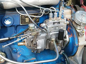
Installation of the fuel pump on the engine d 245
TNVD of the D-245 engine
On the engine D-245 MTZ-892, MTZ-92P installed TNVD-773. The high-pressure fuel pump (TNVD) D-245 is a block design consisting of four pump sections in one housing, having a cam drive of plungers and spool dosing of cyclic fuel supply. TNVD-773 is intended for supplying metered portions of fuel under high pressure to the combustion chambers of diesel cylinders at certain times. The cam shaft of the fuel pump D-245 is driven from the crankshaft of the diesel engine through the distribution gears. The relative position of the gear wheel of the fuel pump drive and the coupling half of the drive is fixed by tightening the nuts installed on the studs of the coupling half. The value of the tightening torque of nuts is 35 ... 50 Nm. The high-pressure fuel pump D-245 MTZ-892, MTZ-92P is combined into one unit with an all-mode regulator and a piston type fuel priming pump. The regulator has a fuel feed corrector, an automatic fuel feed concentrator (at starting speeds) and a pneumatic smoke limiter (boost corrector). The booster pump is mounted on the housing of the high-pressure fuel pump D-245 and is driven by a cam cam eccentric. The working parts of the high-pressure fuel pump D-245 are lubricated with flowing oil coming from the diesel lubrication system. Oil is drained from the pump housing into the diesel crankcase. The newly installed pump on the diesel engine must be filled with oil in an amount of 200 ... 250 cm3. Fill the oil through the oil drain hole pos. 30 (Fig. 1). Fig. 1 - High-pressure fuel pump TNVD 773 diesel D-245 1 - section of the fuel pump; 2 - plate; 3 - flange; 4 - key; 5 - drive coupling half; 6 - a nut of fastening of a half coupling; 7 - cam shaft; 8 - fuel pump housing; 9 - fuel priming pump; 10 - supporting bracket; 11 - a bolt of adjustment of starting feed; 12 - stop lever; 13 - regulator body; 14 - a regulator cover; 15 - cover of the inspection hatch; 16 - a bolt of adjustment of the minimum frequency of rotation; 17 - a bolt of adjustment of the maximum frequency of rotation; 18 - a nut of fastening of sections of the fuel pump; 19 - bypass valve; 20 - fuel supply fitting; 21– oil pipe; 22 - fitting for the removal of fuel from the booster pump to the filter of fine fuel; 23 - a bolt of fastening of the union of a supply of fuel to the priming pump; 24 - boost corrector; 25 - a bolt of the union of an air supply; 26 - control lever; 27 - plug screw adjustment of the nominal fuel supply; 28 - a tube of air discharge; 29 - shutdown electromagnet; 30 - hole drain oil. Maintenance of the high-pressure fuel pump TNVD D-245 During operation of the 773 high-pressure fuel pump, wear and tear of the main parts violates its adjustment parameters. The TNVD D-245 lubricant is centralized from the diesel lubrication system through a special oil pipe. The required oil level in the crankcase is set automatically.
To reduce wear of precision parts, it is not allowed to operate the high-pressure fuel pump without a filter element or with a clogged fine fuel filter. Also, work with fuels having a high water content is not allowed. If necessary, as well as every 120 thousand km of run, it is necessary to remove the fuel injection pump from the MTZ-892, MTZ-92P diesel engine and check the fuel pump on the stand for compliance with the adjustment parameters, as well as the installation angle of the fuel injection on the diesel. Adjust as necessary. Checking and adjusting the high-pressure fuel pump 773 for the installation angle of advancing fuel injection on the D-245 engine If it is difficult to start the diesel engine, smoke exhaust, and also when replacing, installing the fuel pump after checking at the stand every 120 thousand kilometers or repairing the MTZ-892, MTZ-92P diesel engine, be sure to check the installation angle of the fuel injection on the diesel engine. The fuel injection advance setting angle, degrees of crankshaft rotation for the high-pressure fuel pump TNVD 773.1111005-20.05 (D-245 engine) - 2.5 ± 0.5 :
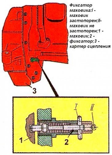
Install the piston of the first cylinder on a compression stroke 40-50 to TDC; - set the regulator control lever to the position corresponding to the maximum fuel supply; - disconnect the high-pressure pipe from the fitting of the first section of the D-245 high-pressure fuel pump and instead connect the control fixture, which is a piece of a high-pressure pipe 100 ... 120 mm long with a compression nut at one end and the second end bent to the side by 150 ... 170 ° in accordance with figure 24; - fill the fuel pump of the TNVD D-245 with fuel, remove air from the low pressure system and create excess pressure with the manual pump until a solid stream of fuel appears from the tube of the control device; - Slowly rotating the diesel crankshaft clockwise and maintaining excessive pressure in the pump head (pumping pump), watch for the outflow of fuel from the control device. At the moment of termination of the outflow of fuel (dropping up to 1 drop in 10 seconds is allowed), stop the rotation of the crankshaft; - in accordance with Figure 2, unscrew the lock from the threaded hole of the back sheet and insert it with the back into the same hole all the way into the flywheel, while the lock must coincide with the hole in the flywheel (this means that the piston of the first cylinder is set to the installation position fuel injection lead angle.  Fig. 2 - Installing the latch in the hole of the back sheet and the D-245 flywheel If the latch does not match the hole in the flywheel, adjust the high pressure fuel pump 773, for which do the following:
Remove the hatch in accordance with Figure 3; - Align the retainer with the hole in the flywheel by turning the crankshaft in one direction or another; - release by 1 ... 1,5 turn of a nut of fastening of a gear wheel of a drive of the fuel pump; - using a wrench, turn the fuel pump roller by the nut counterclockwise until the studs stop in the edge of the groove of the gear wheel of the fuel pump drive; - create excess pressure in the head of the fuel pump D-245 until a continuous stream of fuel appears from the tube of the control device; - turning the pump shaft clockwise and maintaining excessive pressure, monitor the outflow of fuel from the control device; - at the moment of termination of the fuel outflow, stop the rotation of the shaft and fix it by clamping the nuts of fastening of the drive coupling half to the drive gear. Recheck the start of fuel delivery. Disconnect the test fixture and replace the high pressure pipe and manhole cover. Screw the latch into the hole in the back sheet.  Fig. 3 - Fuel pump drive TNVD D-245 1 - manhole cover; 2 - a nut; 3 - hairpin; 4 - special nut; 5 - drive coupling half; 6 - a gear wheel of a drive of the fuel pump Checking D-245 engine injectors for injection start pressure and fuel atomization quality
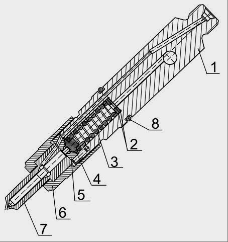 Fig. 4 - D-245 nozzle 1 - nozzle body; 2 - an adjusting washer; 3 - spring; 4 - nozzle rod; 5 - a spacer; 5 - spray gun nut; 7 - a spray; 8 - a sealing ring. Check the D-245 injectors every 120 thousand kilometers. Remove the nozzles from the diesel engine and check them on the stand. The nozzle of the fuel pump of the TNVD 773 D-245 diesel engine is considered to be serviceable if it atomizes fuel in the form of fog from all five holes of the atomizer, without separately dropping drops, solid jets and condensations. The beginning and end of the injection should be clear, the appearance of drops on the tip of the spray is not allowed. Check the spray quality at a frequency of 60-80 injections per minute. If necessary, adjust the D-245 nozzles by changing the total thickness of the adjusting washers 2 (Fig. 4): increasing the total thickness of the adjusting washers (increasing the compression of the spring) increases the pressure, decreasing - lowers. A change in the thickness of the washers by 0.1 mm leads to a change in the pressure of the beginning of the nozzle needle lift by 1.3 ... 1.5 MPa.
The values \u200b\u200bof the pressure of the beginning of injection for injectors: 455.1112010-50 - 24.5 MPa; 172.1112010-11.01 - 25.0 ... 26.2 MPa. Install the nozzles on the diesel. Tighten bolts of a bracket of fastening of nozzles of D-245 evenly in 2-3 receptions. The final tightening torque is 20 ... 25 Nm.
To adjust the quantity and uniformity of fuel supplysections of the pump must do the following. Before adjusting the pump for uniformity and quantity of fuel supply for each section, check:
Pressure tightness of valves by shutting off the fuel supply with the control lever. Fuel leaks are not allowed. In case of leakage, replace the discharge valve assembly;
The fuel pressure in the suction cavity of the fuel pump, which should be 0.07 ... 0.13 MPa;
Lack of air leaks at the joints of the fuel lines.
Adjust the amount of fuel supplied by each section of the pump and. uniformity of feed in sections at a speed of 1200 min -1 in accordance with the adjustment table. Control the unevenness of the fuel supply in accordance with GOST 10578.
| fig. 1 |
Adjustment of the cyclic fuel supply at the rated speed of rotation is carried out using a hard stop 60 (see Fig. 1). When the bolt is screwed in (inside the housing), the feed increases, when it is turned out, it decreases. The fuel supply should be adjusted at maximum torque (700 ... 800 min -1) by changing the position of the corrector screw 71. To achieve the rotation speed corresponding to the off corrector (complete penetration of the corrector rod), it is necessary:
- at an overestimated frequency (more than 800 min) - turn the adjusting screw out of the corrector housing;
- at low speed (less than 700 min -1) - screw the screw into the corrector housing.
The magnitude of the cyclic feed is determined by the stroke of the corrector, which should be equal to 0.5 ... 0.7 mm.
To determine the parameters for adjusting the cyclic feed, it is necessary to determine the cyclic feed in the speed range, expanded in comparison with the adjustment table by 50 min -1 in each direction after 50 min -1. To calculate the maximum correction factor, the largest (from the measured) cyclic transmission must be selected.
The uniformity of the fuel supply and the performance of each section of the pump must be regulated by moving the rotary sleeve relative to the ring gear with a loose clamping screw. When turning the sleeve to the left, the fuel supply by the section increases, when turning the sleeve to the right, it decreases. After adjusting the pump section, tighten the ring gear screw securely.
If it is necessary to change the fuel supply at the same time for all 4 sections, it is allowed to change the position of the hard stop, after which it is necessary to check the start of the regulator and the uniformity of fuel supply in the sections. Check the amount of fuel supply at a maximum idle speed, which should be 22.5 mm 3 cycles at a speed of 1250 min -1. Screw bolt 56 (see Fig. 1) with an idle spring at a maximum idle speed until the free end of the spring touches the main spring lever and lock it with a nut. Check the cyclic fuel supply at a speed of 90 ... 100 min -1, corresponding to the starting mode. The average cyclic fuel supply at this speed should be at least 140 mm / cycle when the control lever is installed all the way to the maximum speed screw. Check the forced complete shutdown of the fuel supply at a speed of 100 min -1 by moving the control lever to the extreme position in side to reduce feed.
Boost adjustment
The beginning of the movement of the rod should occur at an air pressure in the above-diaphragm space equal to 0.005-0.010 MPa. In the absence of pressure in the above-diaphragm space, the average cyclic feed is established by moving the stop 46 (see Fig. 1) and should be 60 ... 70 mm 3 / cycle at a pump cam shaft speed of 550 min -1. The start of movement of the diaphragm 51 (rod 54) must be adjusted by changing the preliminary compression of the spring by screwing or unscrewing the sleeve 50. The movement of the sleeve 50 toward the diaphragm increases the air pressure corresponding to the start of the diaphragm; the movement of the sleeve from the diaphragm reduces the air pressure corresponding to the start of the diaphragm. After adjusting the start of movement of the diaphragm (rod), install pin 49 in the hole of the corrector housing. When installing the pin, make sure that its upper end does not protrude above the upper plane of the CPN housing, for which, if necessary, turn the corrector sleeve 50 in one direction or another by no more than 30 °. The pressure of the beginning of the movement of the diaphragm (rod) must remain within the established limits. The pressure corresponding to the end of the operation of the CPV should be determined by a series of successive measurements of performance in the pump sections at the corresponding speed of the cam shaft of the fuel pump. The end of the CPN operation should be at a frequency of 550 min -1 and a pressure of 0.012 ... 0.015MPa.
How to adjust the fuel injection pump of the D-245 diesel engine and its device we will learn in this article.
 The high-pressure fuel pump is a mechanism that ensures the flow of diesel fuel into the combustion chambers of the cylinders. The fuel pump is among the main structural parts of the diesel injection system.
In this case, the fuel supply is carried out in certain doses and at set intervals. These are two tasks that a high-pressure fuel pump should ideally perform - forcing a clearly calibrated amount of diesel fuel under pressure and determining the assigned injection moment.
The main component of the pump is a plunger pair, it combines a plunger (piston) and a sleeve (cylinder). These elements are produced in factories with extremely consistent accuracy and using the highest quality steel. There is a very small gap between them (precision mating).
According to their design, fuel injection pumps differ:
- in-line pumps - in such variations, the injection of diesel into each cylinder occurs using a separate pair of piston and cylinder;
- distribution pumps - they are equipped, as a rule, with one or a pair of plungers that work on all cylinders;
- main pumps - pump fuel exclusively into batteries.
Injection pump for power units D-245.
Diesel engines of the D-245 model, which are installed on many trucks of the ZIL, MAZ, GAZ and others, are equipped with a 773 marking high-pressure fuel pump.
Design.
The whole mechanism has a block design. TNVD-773 consists of 4 sections located in one housing. Such a device involves cyclic diesel injection, using dosing using a spool. Fuel pumps of this type are combined with a special regulator and a fuel pump in one common unit.
The principle of lubrication.
The lubrication of the working parts of the high pressure fuel pump is carried out thanks to the supply of oil from the main lubrication system. After shutting down, the oil is drained into the crankcase. After each new installation on the fuel pump motor, it is recommended to fill it with oil in an amount of about 250 ml. Filling the high pressure fuel pump with oil is carried out through the drain oil neck. When installing the high pressure fuel pump, the weld plate intended for it should have a clean surface without damage and chips.
TNVD of the diesel engine D-245 - device and adjustments
 On the D-245 engine of ZIL-5301 cars Bychok, GAZ-3309, MAZ-4370 Zubrenok are installed TNVD-773. The high-pressure fuel pump is a block design consisting of four pump sections in one housing, having a cam drive of plungers and spool dosing of cyclic fuel supply.
TNVD-773 is intended for supplying metered portions of fuel under high pressure to the combustion chambers of diesel cylinders at certain times. The camshaft of the fuel pump is driven from the crankshaft of the diesel engine through the distribution gears.
The relative position of the gear wheel of the fuel pump drive and the coupling half of the drive is fixed by tightening the nuts installed on the studs of the coupling half. The value of the tightening torque of nuts is 35 ... 50 Nm.
The D-245 high-pressure fuel pump is combined into one unit with an all-mode regulator and a piston type fuel priming pump.
The regulator has a fuel feed corrector, an automatic fuel feed concentrator (at starting speeds) and a pneumatic smoke limiter (boost corrector). The booster pump is mounted on the housing of the high-pressure fuel pump D-245 and is driven by a cam cam eccentric.
The working parts of the pump are lubricated with flowing oil coming from the diesel lubrication system. Oil is drained from the pump housing into the diesel crankcase. The newly installed diesel pump must be filled with oil in an amount of 200 ... 250 cm3. Fill the oil through the oil drain hole pos. 30 (Fig. 1).
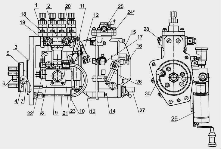
Fig. 1 - Fuel pump TNVD 773 diesel D-245
1 - section of the fuel pump; 2 - plate; 3 - flange; 4 - key; 5 - drive coupling half; 6 - a nut of fastening of a half coupling; 7 - cam shaft; 8 - fuel pump housing; 9 - fuel priming pump; 10 - supporting bracket; 11 - a bolt of adjustment of starting feed; 12 - stop lever; 13 - regulator body; 14 - a regulator cover; 15 - cover of the inspection hatch; 16 - a bolt of adjustment of the minimum frequency of rotation; 17 - a bolt of adjustment of the maximum frequency of rotation; 18 - a nut of fastening of sections of the fuel pump; 19 - bypass valve; 20 - fuel supply fitting; 21– oil pipe; 22 - fitting for the removal of fuel from the booster pump to the filter of fine fuel; 23 - a bolt of fastening of the union of a supply of fuel to the priming pump; 24 - boost corrector; 25 - a bolt of the union of an air supply; 26 - control lever; 27 - tube screw adjustment
nominal fuel supply; 28 - a tube of air discharge; 29 - shutdown electromagnet; 30 - hole drain oil.
Frequent problems and their prevention.
The most common fuel injection pump problem is the uneven and reduced fuel supply. This causes wear of a large group of elements of the mechanism, such as plunger pairs, valves, rails and the crown of the sleeve. For this reason, nozzle throughput is also reduced. The consequence of all this is the loss of power and increased fuel consumption.
The mechanism will wear out even with a delayed fuel injection moment. If the cam shaft, its bearings and keys break down, this leads to an absolute failure of the high-pressure fuel pump or, at the very least, leads to noticeable deviations. Therefore, it is important to ensure that the camshaft nut is tightened sufficiently to avoid such problems, as well as the tightness of all components in general.
Service of the fuel pump of a high pressure of TNVD diesel engines D-245
 During operation of the 773 high-pressure fuel pump, wear and tear of the main parts violates its adjustment parameters. The TNVD D-245 lubricant is centralized from the diesel lubrication system through a special oil pipe. The required oil level in the crankcase is set automatically.
To reduce wear of precision parts, it is not allowed to operate the high-pressure fuel pump without a filter element or with a clogged fine fuel filter. Also, work with fuels having a high water content is not allowed.
If necessary, as well as every 120 thousand kilometers, it is necessary to remove the pump and check it on the bench for compliance with the regulatory parameters, as well as the installation angle of the timing of the fuel injection on the diesel engine. Adjust as necessary.
Adjustment and control of the high-pressure fuel pump 773 for the installation angle of advancing fuel injection on the D-245 engine
If it is difficult to start the diesel engine, smoke exhaust, and also when replacing, installing the fuel pump after checking at the stand every 120 thousand kilometers or repairing the diesel engine, be sure to check the installation angle of the fuel injection on the diesel engine.
The fuel injection advance setting angle, degrees of crankshaft rotation for the high-pressure fuel pump of the high-pressure fuel pump 773.1111005-20.05 - 2.5 ± 0.5
Check the installation angle of the fuel injection lead for the injection pump 773 of the D-245 engine in the following sequence:
- Install the piston of the first cylinder on the compression stroke for 40-50 to TDC;
- set the regulator control lever to the position corresponding to the maximum fuel supply;
- disconnect the high-pressure pipe from the fitting of the first section of the high pressure fuel pump and instead of it connect the control device, which is a segment of a high-pressure pipe with a length of 100 ... 120 mm with a compression nut at one end and the second end bent to the side by 150 ... 170 ° in accordance with the figure 24;
- fill the fuel pump with fuel, remove air from the low-pressure system and create excess pressure with the manual pump until a continuous stream of fuel appears from the tube of the control device;
- Slowly rotating the crankshaft of the D-245 diesel engine of ZIL-5301 cars Bychok, GAZ-3309, MAZ-4370 Cogwheel clockwise and maintaining excessive pressure in the pump head (pumping pump), watch for fuel to flow out of the control device.
- At the moment of termination of the outflow of fuel (dropping up to 1 drop in 10 seconds is allowed), stop the rotation of the crankshaft;
- in accordance with Figure 2, unscrew the lock from the threaded hole of the back sheet and insert it with the back into the same hole all the way into the flywheel, while the lock must coincide with the hole in the flywheel (this means that the piston of the first cylinder is set to the installation position fuel injection lead angle.
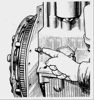
Fig. 2 - Installing the latch in the hole of the back sheet and the flywheel of the D-245 diesel
If the latch does not match the hole in the flywheel, adjust the high pressure fuel pump 773, for which do the following:
- Remove the hatch in accordance with Figure 3;
- Align the retainer with the hole in the flywheel by turning the crankshaft in one direction or another;
- release by 1 ... 1,5 turn of a nut of fastening of a gear wheel of a drive of the fuel pump;
- using a wrench, turn the fuel pump roller by the nut counterclockwise until the studs stop in the edge of the groove of the gear wheel of the fuel pump drive;
- create excess pressure in the head of the fuel pump until a continuous stream of fuel appears from the tube of the control device;
- turning the pump shaft clockwise and maintaining excessive pressure, monitor the outflow of fuel from the control device;
- at the moment of termination of the fuel outflow, stop the rotation of the shaft and fix it by clamping the nuts of fastening of the drive coupling half to the drive gear.
Recheck the start of fuel delivery. Disconnect the test fixture and replace the high pressure pipe and manhole cover.
Screw the latch into the hole in the back sheet.
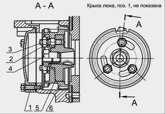
Fig. 3 - Drive fuel pump fuel pump engine D-245
1 - manhole cover; 2 - a nut; 3 - hairpin; 4 - special nut; 5 - drive coupling half; 6 - a gear wheel of a drive of the fuel pump
 The fuel injection plate must be clean; nicks and other damage to the plate are not allowed.
The fuel pump gasket must not have visible damage.
At installation of the fuel pump it is necessary to combine labels of a gear wheel of a drive of the fuel pump and spline flange.
The splined flange of the gear of the fuel pump should freely, without jamming, be located on the splines of the sleeve of the fuel pump roller.
Bolts of fastening of a flange of a gear wheel of the fuel pump should be tightened by the moment 18 ... 25 Nanometers.
When installing the fuel pump, it is necessary to check the angle of advance of fuel injection.
This is done in the following sequence:
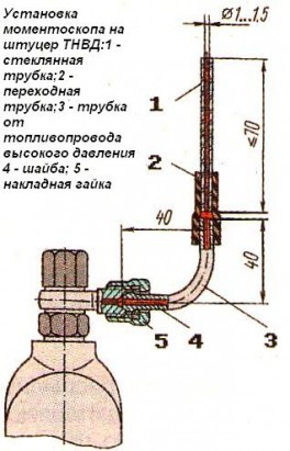
- Disconnect the high-pressure pipe from the fitting of the first section and connect a momentoscope instead (fig. 1).
- Turn the diesel crankshaft with a key in a clockwise direction until a fuel momentoscope emerges from the glass tube without air bubbles.
- remove some of the fuel from the glass tube by shaking it.
- Turn the crankshaft counterclockwise by 30 .. .40 °.
- Slowly turning the diesel crankshaft clockwise to monitor the fuel level in the tube, at the moment of the start of the fuel lift, stop the rotation of the crankshaft.
- remove the manhole cover;
- unscrew bolts 1, 2 and 3 (Fig. 3) and loosen bolt 3 by ½ ... 1 revolution (do not turn out the bolt);
- align the lock pin 2 (see. Fig. 2) with the hole in the flywheel, turning the crankshaft of the diesel engine in one direction or another; using a wrench, turn the fuel pump roller and spline flange by the nut until the moment the fuel begins to rise in the glass tube 1 (see Fig. 1) of the momentoscope;
- install the bolts 1,2 and 3 (see Fig. 3) into the matching holes, trying to arrange them as evenly as possible around the circumference;
5. Tighten bolt 3 first, then bolts 1 and 2;
- replace the high pressure pipe and remove the retainer rod from the hole in the flywheel;
- replace the sunroof.
The combination of the splines of the fuel pump bushing and the splined flange when installed on a diesel engine is provided by turning the crankshaft of the diesel engine or the cam shaft of the pump.
Nozzles of the same group should be installed on the diesel.
Sealing gaskets on the contact side with the nozzles should be lubricated with US-1 GOST 33-51 solid oil.
The nozzle mounting bolts must be tightened to a torque of 20 ... 25 Nm.
High pressure pipes must be fixed at a distance of 10 ... 15 mm from the union nuts with clamps with gaskets.
Pipes of low pressure fuel before installing on a diesel engine should be blown with compressed air.
Checking D-245 diesel injectors for injection start pressure and fuel atomization quality

Fig. 4 - D-245 engine nozzle
1 - nozzle body; 2 - an adjusting washer; 3 - spring; 4 - nozzle rod; 5 - a spacer; 5 - spray gun nut; 7 - a spray; 8 - a sealing ring.
Check the injectors every 120 thousand kilometers. Remove the nozzles from the diesel engine and check them on the stand. The fuel injection pump injector 773 is considered serviceable if it atomizes fuel in the form of fog from all five nozzle openings, without separately dropping drops, solid jets and condensations.
The beginning and end of the injection should be clear, the appearance of drops on the tip of the spray is not allowed. Check the spray quality at a frequency of 60-80 injections per minute.
If necessary, adjust the nozzles by changing the total thickness of the adjusting washers 2 (Fig. 4): increasing the total thickness of the adjusting washers (increasing the compression of the spring) increases the pressure, decreasing - lowers. A change in the thickness of the washers by 0.1 mm leads to a change in the pressure of the beginning of the nozzle needle lift by 1.3 ... 1.5 MPa.
The values \u200b\u200bof the pressure of the beginning of injection for injectors: 455.1112010-50 - 24.5 MPa; 172.1112010-11.01 - 25.0 ... 26.2 MPa. Install the nozzles on the diesel. Tighten bolts of a bracket of fastening of nozzles evenly in 2-3 receptions. The final tightening torque is 20 ... 25 Nm.
Injector Test.
In addition to checking the high-pressure fuel pump, an integral part of servicing the D-245 engine is nozzle testing. The starting and ending moments of the injection should always be clear. If the spray tip has the remaining drops, then a deviation has occurred. This factor is checked during cyclic injection with an amplitude of 60-80 injections / min.
Adjusting the nozzles is quite simple by leveling the thickness of the adjusting washer. The stronger the spring is compressed, the more the pressure increases, and vice versa. To deviate pressure by 1.5 MPa to one side, a decrease or increase in the thickness of the washer by 0.1 mm is required.
The cost of fuel injection pump and components.
The new fuel pump will cost the buyer 25-50 thousand rubles, depending on the manufacturer. Take, for example, the company MOTORPAL - high-pressure fuel pumps of its production have a price of 25-35 thousand rubles.
It is also worth mentioning the approximate cost of the main spare parts adequate for the current market, which may require replacement:
- nozzles (1500-3000 rubles / pcs.);
- mounting plate (3000-5000 r);
- gear drive TNVD (3000-5000 r);
- TNVD gearbox shaft for D-245 (3000-5000 r);
- VD fuel line (up to 1000 r);
- fuel pump (1500-3000 r).
A source
avtodisel.ru
tnvd-resurs.ru
avtomechanic.ru