Tightening torques of the KAMAZ engine 740 euros 2. Transport: history and modernity
TO category:
Car Maintenance
Technical conditions for the assembly of the KamAZ-740 engine
Installing cylinder liners and guide pushers.
The upper O-rings must be installed on the cylinder liners without twisting and excessive stretching.
Before installing the sleeves in the block, the TsIATIM type grease must be applied to the entry chamfers of the block and sleeves. The sleeves should be inserted into the unit carefully by hand, not allowing the o-rings protruding from the grooves to be cut off.
On the upper non-working end of each sleeve on the side facing the fan, it is necessary to put the cylinder number.
The guides of the pushers should come to the assembly complete with pushers. All guides and pushers installed on one engine must have the size according to the working drawing or repair. The guides should be installed on the pins of the cylinder block and bolted. The tightening torque of the bolts should be 7.5-9.5 kgf-m.
Assembly and installation of a camshaft. The camshaft must be assembled with the bearing housing and gear. Before assembling with the bearing housing, the back support journal of the shaft and the housing sleeve must be wiped with a napkin and greased with clean engine oil.
Press the gear, preheated to a temperature of (100 ± 10) ° С, onto the shaft journal as far as it will go. The clearance between the gear and the bearing housing should be 0.25-0.30 mm.
When installing the camshaft in the cylinder block, lubricate the bushings of the bearings and the journal journals with clean engine oil. The camshaft should be installed carefully; damage to the working surfaces of the bushings is not allowed.
Assembly and installation of the crankshaft. Before assembling, it is necessary to carefully blow the crankshaft with compressed air. In the shaft cavity, press in and expand the plugs, and insert a screwdriver into the oil channel of the front end, As shown in Fig. 2. The depth of the end face of the screwdriver from the end of the shaft should be at least 56.5 mm. The tightening torque of the screwdriver should be 5-6 kgf-m. Check the tightness of the plugs by pressure testing the cavities with diesel fuel under a pressure of 2 kgf / cm2. Leakage of fuel is allowed no more than 20 g / min for one plug. After checking, to remove fuel, it is necessary to blow out the channels and cavities of the shaft. It is allowed to check the tightness of plugs with oil at a temperature of 40-50 ° C under a pressure of 10 kgf / cm2; oil leakage for one plug should not be more than 20 g / min. Reinstallation of used plugs is not allowed.

Fig. 1. Joints of the cylinder head and liner, head and cylinder block of the KamAZ engine: 1 - support ring; 2 - cylinder head gasket; 3-cylinder head; 4 - rubber head gasket; 5 - cylinder block; 6 - sealing ring of the sleeve; 7- sleeve

Fig. 2. Installing plugs for the channels of the crankshaft: 1 - front counterweight; 2-gear oil pump drive; 3-stub; 4 - sleeve; 5 - cap screwdriver
The mounting pins must be pressed into the crankshaft so that the pin on the front end of the shaft protrudes by 7 mm and the rear by 10 mm.
Heat the gears and balances before pressing to a temperature of 105 ° C. Pressing to the stop. Counterweights are made with an imbalance of 13,500 g-cm relative to the axis of the hole with the direction of action along the axis of symmetry of the counterweight. Deviation from a given imbalance should not exceed 15 gf-cm in any direction.
The dimensions of the main bearing shells must correspond to the dimensions of the crankshaft necks and the seats in the cylinder block. Before installing the crankshaft in the block, the working surface of the main bearing shells and the main journals must be lubricated with clean engine oil. Install the axial half rings of the crankshaft in the recesses of the rear main bearing so that the sides with the grooves are adjacent to the axial ends of the shaft. Tighten the main bearing cap bolts in accordance with the instructions given in the technical specifications for repair of the afterburner.
Installation of timing gears. Gears should be installed on labels, as shown in fig. 78. Tighten bolts of fastening of an axis of a leading gear wheel of a camshaft drive to the block in two stages (preliminary and final) with a torque of 5.0-6.2 kgf-m. Tighten the camshaft pinion roller bearing mounting bolt to 9-10 kgf-m.
The circumferential clearance in the engagement of the timing gears when the engine is in working condition should be 0.1-0.3 mm. Measure the circumferential clearance with a probe at three points (at least).
Assembly and installation of flywheel housing. The crankcase is assembled with a front bearing housing and a sleeve for the rear end of the crankshaft. Before installing the crankcase, the cylinder block along the perimeter of the flywheel crankcase gasket may be lubricated with a thin layer of UT-2 constalin or with lubricants 1-13, TsIATIM -201. Tighten the flywheel housing bolts to a torque of 9-11 kgf-m.
The radial runout of the landing diameter and the axial end of the flywheel housing under the clutch housing relative to the axis of the crankshaft should not exceed 0.4 mm.
Assembly and installation of the piston with a finger and a connecting rod. A piston with a finger and a connecting rod is assembled after heating the piston to 80 -) (10 ° C. The hole in the connecting rod under the finger and the finger itself must be liberally lubricated with engine oil. The finger is installed by hand (pressing is not allowed).
Recesses for valves on the piston and grooves for the mustache of the liners on the connecting rod must be positioned in one direction. The piston pin retaining rings must securely lock it in the piston against axial movement.
On the connecting rod cap, it is necessary to knock out the cylinder serial number, having previously checked the pairing of the cap with the connecting rod.
Install compression and oil scraper rings on the piston using a special tool. Install the oil scraper ring in series: first insert the spring expander into the groove, then put on the ring so that the expander joint is at an angle of 180 ° to the ring lock.

Fig. 3. Installation of distribution gears: 1 - drive gear; 2,3 - intermediate gears; 4 - a camshaft gear; 5 - gear drive fuel pump
Then install the compression ring coated with Mplia ^ and, and the last - the compression ring coated with chrome. Locks adjacent rings to part in opposite directions.
Install kits with pistons and rings assembly on the engine in accordance with the cylinder numbers stamped on the connecting rod cover. The cylinder numbering is shown in fig. 4. When installing the piston in the sleeve, the recesses under the valves on the piston should be offset closer to the axis of the crankshaft.
The total gap between the ends of the lower heads of the connecting rods and the cheeks of the crankshaft (axial play) should be at least 0.15 mm. The protrusion of the piston bottom above the shoulder of the liner should be in the range of 0.5-0.7 mm.
The bolts securing the connecting rod caps must be tightened to an extension of 0.25-0.27 mm.
Assembly and installation of a flywheel. The flywheel must be assembled with a gear rim and an installation sleeve. When installing on the flywheel, the toothed rim must be heated to a temperature of 230 ° C. The mounting sleeve must be assembled with the input shaft collar and pressed into the flywheel until it stops.
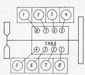
Fig. 4. The scheme of the numbering of the cylinders of the KAMAZ engine and the location of the sections of the injection pump
Fig. 5. Flywheel assembly of the KamAZ engine: 1 - gear ring; 2 - flywheel; 3 - a persistent ring; 4 - installation sleeve; 5 - an epiploon of a primary shaft of a transmission
Before installing the flywheel on the engine, press the input shaft bearing of the gearbox into the hole in the rear end of the crankshaft and put 15 g of grease No. 153. Tighten the flywheel mounting bolts sequentially in two stages (preliminary and final) with a torque of 15-17 kgf-m. The runout of the working surface of the flywheel and the near-roll surface under the clutch cover, measured at maximum diameters relative to the axis of the crankshaft, should not exceed 0.25 mm.
Assembly and installation of cylinder heads. The cylinder head must be thoroughly blown with compressed air before assembly. The support ring of the gas joint after installation in the head must be crimped with a force of 4500 kgf. The protrusion of the plane of the ring from the head after crimping should be 0.122-0.230 mm. The measurement difference for one head should not exceed 0.08 mm. The protrusion of the gas joint ring should not have any burrs or nicks.
Valve seating must be airtight. Leak test with dry air at a pressure of 1.5 kg / cm2. Permissible air leakage should not exceed 3.6 cm / min. Valves must be securely fixed with crackers.
Before installing the cylinder head, the interface plane of the block and the head, as well as the gasket, must be wiped and blown with compressed air. The cylinder head rubber o-rings should be installed with the flat side facing the cylinder block. The cylinder head should fit freely onto the dowel pins without impact. The threads of the cylinder head bolts must be lubricated with a thin layer of graphite grease. The bolts are tightened in the sequence shown in fig. 81. The bolts must be tightened in at least three steps: 1st — 4 kgf-m; 2nd - 124-15; 3rd - 19-Н21 kgf-m (limit values).

Fig. 6. The order of an inhaling of bolts of fastening of a head of the cylinder of the KamAZ engine
TO Category: - Car Maintenance
Each head of the Kamaz-740 block is mounted on two locating pins, pressed into the cylinder block, and is fastened with four alloy steel bolts.
One of the locating pins simultaneously serves as a hub for oil supply to lubricate the rocker arms. The sleeve is sealed with rubber rings.
Compared to the engine head 740.10, the KamAZ-740 cylinder head has a larger hole for draining engine oil from under the valve cover into the rod cavity. The windows of the inlet and outlet channels are located on opposite sides of the cylinder head.
The inlet channel has a tangential profile to ensure optimal rotational movement of the air charge, which determines the parameters of the working process and environmental performance of the engine, so replacement with the cylinder heads of the 740.10 engine is not allowed.
Cast iron seats and ceramic-metal valve guides are pressed into the cylinder head of the Kamaz-740. The valve seats have an increased interference fit compared to the 740.10 engine seats and are fixed with a sharp edge.
The outlet seat and valve are profiled to provide less resistance to exhaust emissions. The use of an exhaust valve 740.10 is not recommended.
The joint "cylinder head - liner" Kamaz-740 (gas joint) is unlined. A steel seal ring is pressed into the bored groove on the lower plane of the head.
Through this ring, the Kamaz-740 cylinder head is mounted on the sleeve collar. The tightness of the seal is ensured by high precision machining of the mating surfaces of the sealing ring and cylinder liner.
The sealing ring additionally has a lead coating to compensate for microroughnesses of the sealing surfaces.
1 - cylinder head, 2 - cylinder head gasket, 3 - cylinder head bolt, 4 - cylinder head cover, 5 - cylinder head bolt, 6 nipple gasket, 7 - gas joint seal, 8 - intake valve, 9 - seat valve, 10 - valve guide bush, 11 - washer of valve springs, 12 - outer and inner valve springs, 13 - plate of valve springs, 14 - plate of valve spool, 15 - valve cracker, 16-seal sleeve, 17 - inlet valve
The valve mechanism and nozzle are located in the cylinder heads. The valve mechanism of the head is closed by an aluminum cover sealed by a gasket. Cast iron seats and ceramic-metal valve guides are bored after they are pressed into the head.
Each head is attached to the cylinder block with four bolts. To avoid a violation of the tightness of the gas joint, the bolts are tightened in a cross pattern in three steps.
The inlet and outlet channels are located on opposite sides of the head. When looking at the engine from the side, the intake valves of the heads are on the right, and the exhaust valves are on the left.
The inlet channel has a tangential profile, providing swirling air movement in the cylinder, improving mixture formation and accelerating the combustion process of the injected fuel. The nozzle socket is located on the side of the exhaust valve at an angle to the axis of the cylinder.
Dismantling the engine block head
To remove the cylinder head have to quite often. At least every 40-50 thousand kilometers. So the KamAZ engine is structurally designed. The cause is leaking coolant or oil. Dismantling the cylinder head will also be required to repair the piston group or the gas distribution mechanism.
Let's take a step-by-step and detailed look at the process of dismantling the head of the KamAZ 740 engine block.
1. Drain at least half the volume of coolant from the cooling system.
2. To dismantle the cylinder heads of some cylinders, it will be necessary to dismantle the coolant expansion tank and compressor.
3. Remove the intake and exhaust manifolds, as well as unscrew all interfering fuel supply pipes.
4. We turn off a bolt of fastening of a cover of a head of the block with a key on 13.

5. Remove the cover and gasket.
 6. If you need to remove only one head, you will have to remove the cover from the adjacent block head so that its protrusion does not interfere with dismantling.
 7. To dismantle the cylinder head of the fourth and eighth cylinders, you will need to unscrew the nuts securing the cab springs with a 17 key and take them to the side along with the shock absorbers.
 8. It is desirable to fix the gas distribution mechanism rods, for example, by interconnecting them in order to avoid falling into the pallet when removing the cylinder head.

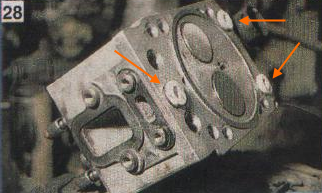
9. Unscrew the four bolts securing the head to the block with a socket wrench or socket wrench at 19.
 10. Remove the head of the block by prying with a mounting spatula and at the same time swinging it by inserting the bolts of the fastening of the winch into the hole.
11. The head should be cleaned of dirt and carbon deposits. After that, replace the three o-rings ("barrels") of the water holes.
 O-rings are included in the repair kit for mechanical rubber goods of the head of the KamAZ 740 engine block. In the vocabulary vocabulary of auto-makers there is their name - a keg.

12. Put a new sealing ring on the sleeve of the oil channel.
 13. Install a new cylinder head gasket on the engine block and put the rods in place.
 14. Replace the block head. The cylinder head bolts should be tightened crosswise in three steps.
The final tightening torque of the bolts of the KamAZ 740 engine block head is 16-18 kgf * m.

Repair kit gaskets RTI engine block heads
The kit consists of:
1.740.1003 040 O-ring, oil channel - 16 pcs.
2. 740.1003 214-04 O-ring (cylinder head) "barrel", is installed in the holes of the coolant channels - 24 pcs.
3. 740.1003 213-26 Gasket gasket cylinder head - 8 pcs.
4. 740.1003270 Gasket, sealing of the cylinder head cover - 8 pcs.

Cylinder head gaskets can be old and new designs.

Old cylinder head gasket

Repair engine head
Given the interchangeability of the heads of the KamAZ 740 engine block, repair is preferable to replacing the cylinder head with a new one.
If necessary, repairs are often carried out:
- Replacing valve seats.
- Seat processing - lapping valves.
- Saddle boring .
- Plane recovery
Crank mechanism of KamAZ engines 740.11-240, 740.13-260, 740.14-300
Crankshaft of KamAZ 740.11-240, 740.13-260, 740.14-300 engines
Crankshaft (see fig.) is made of stainless steel and has five main and four connecting rod necks, hardened by HDTV, which are connected by cheeks and mate with them by transition fillets. For uniform alternation of working strokes, the crankshaft connecting rod journals are arranged at an angle of 90 °.
Crankshaft : 1 - front crankshaft counterweight; 2 - rear crankshaft counterweight; 3 - gear drive oil pump; 4 - a gear drive of a gas distribution mechanism; 5.6 - key; 7 - pin; 8 - nozzle; 9 - lightening holes; 10 - holes for supplying oil in the main necks; 11 - holes for supplying oil to the connecting rod journals .
Two connecting rods are attached to each crank pin. connecting rod: one for the right and one for the left row of cylinders ( Connecting rod ).
The oil supply to the connecting rod journals is made from the holes in the main journals 10 by straight holes 11.
To balance the forces of inertia and reduce vibrations, the crankshaft has six counterweights, stamped at the same time with the cheeks of the crankshaft. In addition to the main counterweights, there are two additional removable counterweights 1 and 2, pressed onto the shaft, while their angular location relative to the crankshaft is determined by keys 5 and 6 ( fig. Crankshaft ).
Ball bearing 5 is pressed into the bore of the crankshaft shank ).

A nozzle 8 is screwed into the cavity of the front toe of the crankshaft, through the gauge hole of which the spline power take-off roller is lubricated to the hydraulic clutch drive.
From axial displacements, the crankshaft is fixed by two upper half rings and two lower half rings 2 ( Fig. Installation of persistent half rings and crankshaft bearing shells ) installed in the grooves of the rear main support of the cylinder block, so that the side with grooves is adjacent to the thrust ends of the shaft. On the front and rear socks of the crankshaft ( fig. Crankshaft ) The gear 3 of the pump oil drive and the drive gear 4 of the camshaft drive are installed. The rear end of the crankshaft has eight threaded holes for the flywheel bolts, the front toe of the crankshaft has eight holes for attaching the vibration damper.
The seal of the crankshaft is carried out with a rubber sleeve 8 ( Fig. Installing the flywheel and crankshaft seal ), with an additional sealing element - anther 9. The cuff is placed in the flywheel housing 4. The cuff is made of fluororubber according to the technology of forming the working sealing edge directly in the mold.
The diameters of the necks of the crankshaft: radical 95 ± 0,011 mm. connecting rod 80 ± 0.0095 mm.
Recovery kamAZ engine Eight repair liner sizes are provided. The designation of the crankshaft bearing shells, the diameter of the crankshaft main neck, the bore diameter in the cylinder block for these shells are shown in Appendix 1.
The designation of the liners of the lower connecting rod head, the diameter of the connecting rod neck of the crankshaft, the diameter of the holes in the lower connecting rod head for these liners are shown in Appendix 2.
The bushings 7405.1005170 P0, 7405.1005171 P0, 7405.1005058 P0 are used when restoring the engine without grinding the crankshaft. If necessary, the crankshaft journals are polished. The tolerances on the diameters of the necks of the crankshaft, the holes in the cylinder block and the holes in the lower head of the connecting rod during engine repair should be the same as the nominal sizes of new engines.
Main and connecting rod bearings of KamAZ 740.11-240, 740.13-260, 740.14-300 engines
Indigenous and connecting rod bearingsmade of steel tape coated with a layer of lead bronze 0.3 mm thick, a layer of lead-tin alloy 0.022 mm thick and a tin layer 0.003 mm thick. Top 3 ( Fig. Installation of persistent half rings and crankshaft bearing shells ) and lower 4 indigenous liners bearingsnot interchangeable. In the upper liner there is a hole for oil supply and a groove for its distribution. Both liners 4 of the lower connecting rod head are interchangeable.
From turning and lateral displacement, the liners are fixed by the protrusions (mustache) included in the grooves provided in the unit’s beds, covers bearings and in the connecting rod beds. The liners have structural differences aimed at increasing their performance during forcing engine turbocharging, while changing the marking of the liners to 7405.1004058 (connecting rod), 7405.1005170 and 7405.1005171 (indigenous).
Therefore, when carrying out repairs, it is not recommended to replace the liners with serial ones with the marking 740.100 .., since this will significantly reduce the resource engine.
Installation of persistent half rings and liners of bearings of the crankshaft: 1 - half ring of the thrust bearings of the crankshaft; 2 - lower ring of the thrust bearing of the crankshaft; 3 - top bearing shell of the crankshaft; 4 - lower crankshaft bearing shell; 5 - cylinder block; 6 - the back cover of the crankshaft bearing; 7 - a cranked shaft.
Covers of main bearings of engines KAMAZ 740.11-240, 740.13-260, 740.14-300
Covers main bearings (Fig. Installing crankshaft bearing caps ) are made of ductile iron of the VCh50 brand. The lids are fastened with the help of vertical and horizontal coupling bolts 3, 4, 5, which are tightened according to a certain pattern with a regulated torque.

Installation of crankshaft bearing caps: 1. Crankshaft bearing cap; 2. Crankshaft; 3. Bolt of fastening; 4. Bolt of coupling fastening of a cover of the bearing left; 5. A bolt of coupling fastening of a cover of the bearing right; 6. Washer 7. Block.
The connecting rod of KamAZ engines 740.11-240, 740.13-260, 740.14-300
Connecting rod (see pic.)steel, forged, rod 1 has an I-section. The upper head of the connecting rod is one-piece, the lower one is made with a straight and flat connector. Connecting rodfinally processed complete with cover 2, so the connecting rod covers are not interchangeable.
A steel-bronze bushing 3 is pressed into the upper head of the connecting rod, and replaceable liners 4 are installed in the lower head. The cover of the lower connecting rod head is fastened with nuts 6, screwed onto bolts 5, previously pressed into the connecting rod shaft. The connecting rod bolts are tightened according to the scheme defined in Appendix 8. The mating marks are applied on the cover and rod of the connecting rod - three-digit serial numbers. In addition, the cylinder serial number is knocked out on the connecting rod cover.
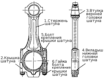
Connecting rod
Flywheel of engines KAMAZ 740.11-240, 740.13-260, 740.14-300
Flywheel 1 (see pic . Flywheel ) secured with eight bolts 7 ( ), made of alloy steel with a twelve-headed head, at the rear end of the crankshaft and precisely fixed with two pins 10 and an installation sleeve 3 ( see pic . Flywheel ).

Flywheel
Installing the flywheel and the seal of the crankshaft: 1 - flywheel; 2 - cylinder block; 3 - a cranked shaft; 4 - flywheel housing; 5 - a bearing of a primary shaft of a transmission; 6 - washer; 7 - flywheel mounting bolt; 8 - a cuff of consolidation of a cranked shaft; 9 - boot cuff; 10 - a pin adjusting a flywheel.
In order to avoid surface damage flywheel a washer 6 is installed under the bolt heads ( Fig. Installing the flywheel and crankshaft seal cuffs ) The magnitude of the tightening torques of the flywheel mounting bolts is shown in Appendix 8. A gear ring 2 is pressed onto the machined cylindrical surface of the flywheel, with which the starter gear engages when starting the engine ( see pic . Flywheel ).
When performing adjustment work to set the lead angle of fuel injection and the values \u200b\u200bof thermal clearances in the valves flywheel fixed with a latch ( Fig. Handwheel Lock Knob Positions ).

Positions of the handle of the flywheel retainer: a) - during operation; b) - during adjustment, in engagement with the flywheel.
Moreover, the design has the following main differences from the serial:
- the angle of the groove under the retainer on the outer surface of the flywheel has been changed;
- the diameter of the bore is increased to accommodate the washer under the flywheel bolts.
Considered kamAZ enginescan be equipped with various types of clutches. On the fig. Flywheel the handwheel for diaphragm clutch is shown.
Torsional vibration damper of KamAZ 740.11-240, 740.13-260, 740.14-300 engines
Torsion damper secured with eight bolts 2 ( fig. Installing a torsional vibration damper ) on the front toe crankshaft . In order to avoid damage to the surface of the damper body, a washer 5 is installed under the bolts. Extinguisherconsists of a housing (see figure) in which a flywheel is installed with a clearance. Outside, the damper body is covered with a lid. Tightness is ensured by rolling (welding) at the junction of the damper body and cover. Between the damper body and the flywheel there is a highly viscous silicone fluid dosed before filling the lid.
The damper is centered by a washer welded to the body ( fig. Torsional vibration damper ) Damping torsional vibrations of the crankshaft occurs by braking the damper body, mounted on the toe of the crankshaft, relative to the flywheel in a silicone fluid environment. In this case, the braking energy is released in the form of heat. During repair work, it is strictly forbidden to deform the case and the damper cover. The damper with a deformed body or cover is not suitable for further use.

Installation of a torsional vibration damper of the crankshaft: 1 - damper; 2 - damper bolt; 3 - coupling for power take-off; 4 - a coupling bolt; 5 - washer; 6 - a cranked shaft; 7 - cylinder block

Torsional vibration damper
The piston of engines KAMAZ 740.11-240, 740.13-260, 740.14-300
Piston 1 ( ) cast from aluminum alloy with an insert of wear-resistant cast iron under the upper compression ring.

In the head piston made toroidal combustion chamber with a displacer in the Central part, it is offset relative to the axis piston5 mm away from the grooves under the valves.
The lateral surface is a complex oval-barrel-shaped with an understatement in the area of \u200b\u200bthe holes under the piston pin. The skirt is coated with graphite.
A groove is made in its lower part, which eliminates contact between the piston and the cooling nozzle when it is in the correct position.
Piston It is completed with three rings, two compression and one oil scraper. Its distinctive feature is the reduced distance from the bottom to the lower end of the upper groove, which is 17 mm. On the kamAZ engines In order to ensure fuel economy and environmental performance, selective selection of pistons for each cylinder according to the distance from the axis of the piston pin to the bottom is applied. According to the specified parameter, the pistons are divided into four groups 10, 20, 30 and 40. Each subsequent group differs from the previous one by 0.11 mm.
IN spare parts pistons of the greatest height are supplied, therefore, in order to avoid possible contact between them and the cylinder heads in case of replacement, it is necessary to control the piston clearance. If the gap between the piston and the cylinder head after tightening the bolts of its fastening is less than 0.87 mm, it is necessary to cut the piston bottom by an amount that is missing to this value. Pistons 740 engines.11, 740.13 and 740.14 differ from each other in the form of grooves for the upper compression and oil scraper rings. (see sections compression and oil scraper rings). Installation of pistons from engines KAMAZ 740.10 and 7403.10 are not allowed. Installation of pistons with piston rings is allowed 740 engines.13 and 740.14 on the engine 740.11. I
Connecting rod piston
Piston with connecting rod ( fig. Piston with rings assembly with connecting rod ) are connected by a finger 3 of a floating type, its axial movement is limited by retaining rings 6. The finger is made of chromium-nickel steel, the hole diameter is 22 mm. The use of fingers with a 25 mm hole is unacceptable, as this disrupts the balancing of the engine.
Compression rings of KamAZ 740.11-240, 740.13-260, 740.14-300 engines
Compression rings (fig. Piston with rings assembly with connecting rod ) are made of high strength, and oil scraper of gray cast iron. On the 740 engine.11 cross-sectional shape compression rings one-way trapezoid, during installation, the inclined end with the mark "top" should be located on the piston bottom side. On the 740 engines.13 and 740.14 the upper compression ring has the cross-sectional shape of a double-sided trapezoid with a sample at the upper end, which should be located on the piston bottom side.
Piston with connecting rod and rings assembly: 1 - piston; 2 - oil scraper ring; 3 - a piston finger; 4, 5 - compression rings; 6 - a lock ring.
The working surface of the upper compression ring 4 is coated with molybdenum and has a barrel-shaped shape. Chrome is applied to the working surface of the second compression 5 and oil scraper rings 2. Its shape on the second ring is a cone with a bias towards the bottom, according to this characteristic feature the ring is called "minute". Minute rings are used to reduce oil consumption for waste, their installation in the upper groove is not permissible.
Oil scraper ring of engines KAMAZ 740.11-240, 740.13-260, 740.14-300
Oil scraper ring box-type with a spring expander having a variable pitch of turns and a polished outer surface. The middle part of the expander with a smaller pitch of turns when installed on the piston should be located in the ring lock. On the engine models 740 .11 ring height - 5 mm and on 740 engines.13 and 740.14 ring height 4 mm.
Installation piston rings from other models kAMAZ engines may lead to increased oil consumption for waste.
To exclude the possibility of using non-interchangeable parts of the cylinder-piston group during repair work, it is recommended to use repair kits:
- 7405.1000128-42 - for the engine 740.11-240;
- 740.13.1000128 and 740.30-1000128 - for engines 740.13-260 and 740.14-300.
The repair kit includes:
- piston;
- piston rings;
- piston pin;
- piston pin retaining rings;
- cylinder liner;
- cylinder liners.
Injectors for cooling engines KAMAZ 740.11-240, 740.13-260, 740.14-300
Cooling nozzles (fig. Installing the liner and piston cooling nozzle ) are installed in the crankcase of the cylinder block and provide oil from the main oil line when it reaches a pressure of 0.8 - 1.2 kg / cm2 (the valve located in each of the nozzles is adjusted to this pressure) into the internal cavity pistons.
During assembly kamAZ engine it is necessary to control the correct position of the tube nozzles relative to the cylinder liner and piston. Contact with the piston is not permitted.
![]()
Source of information Website: http: //www.avtokama.ru/files/teh/dvigatel1.html
The internal combustion engine structurally has a large number of mating parts that experience significant loads during operation. For this reason, assembling the motor is a responsible and complex operation, for the successful completion of which the process should be followed. The operability of the entire power unit directly depends on the reliability of fixation and the accuracy of fit of individual elements. For this reason, the important point is the accurate implementation of the design mates between the mating surfaces or friction pairs. In the first case, we are talking about fastening the cylinder head to the cylinder block, since the bolts must be pulled with a strictly defined force and in a clearly defined sequence.
As for loaded rubbing pairs, increased requirements are put forward for fixing the connecting rod and main bearings (main and connecting rods). After engine repair during the subsequent assembly of the power unit, it is very important to observe the correct tightening torque for the main and connecting rod engine liners. In this article, we will examine why it is necessary to tighten the liners with a strictly defined effort, and also answer the question, what is the tightening torque of the main and connecting rod bearings.
What are plain bearings
For a better understanding of why engine liners need to be tightened to a specific point, let's take a look at the functions and purpose of these elements. To begin with, these sliding bearings interact with one of the most important parts of any ICE -. In short, the reciprocating motion in the cylinder is converted to rotational motion precisely because of the crankshaft. The result is a torque that is ultimately transmitted to the wheels of the car.
The crankshaft rotates constantly, has a complex shape, experiences significant loads and is an expensive part. To maximize the life of the element in the design, connecting rod and main bearings are used. Given the fact that the crankshaft rotates, as well as a number of other features, conditions are created for this part that minimize wear.
In other words, the engineers abandoned the decision to install conventional ball bearings or roller type bearings in this case, replacing them with main and connecting rod bearings. Main bearings are used for crankshaft main journals. Connecting rod liners are installed in the place of connecting the connecting rod with the neck of the crankshaft. Often, the main and connecting rod bearings are made according to the same principle and differ only in internal diameter.
For the manufacture of liners, softer materials are used compared to those from which the crankshaft itself is made. Also, the liners are additionally coated with an antifriction layer. In the place where the liner is mated with the neck of the crankshaft, lubricant (engine oil) is supplied under pressure. The specified pressure is provided by the oil pump. It is especially important that there is a necessary clearance between the crankshaft journal and the sliding bearing. The lubrication quality of the rubbing pair will depend on the size of the gap, as well as the pressure indicator of the engine oil in the lubrication system of the engine. If the clearance is increased, then the lubricant pressure decreases. As a result, there is a rapid wear of the crankshaft journals, as well as other loaded nodes in the ICE device. In parallel with this, a knock appears in the engine.
We add that a low indicator of oil pressure (in the absence of other reasons) is a sign that you need to grind the crankshaft, and the engine liners themselves must be changed taking into account the repair size. For repair liners, an increase in thickness of 0.25 mm is provided. As a rule, the repair dimensions are 4. This means that the diameter of the repair liner in the last dimension will be 1 mm. less than standard.
The slide bearings themselves consist of two halves in which special locks are made for proper installation. The main task is to create a gap between the shaft journal and the liner, which is recommended by the engine manufacturer.
As a rule, a micrometer is used for measuring the neck; the inner diameter of the connecting rod bearings is measured with an internal caliper after assembly on the connecting rod. Also, for measurement, you can use the control strip of paper, using copper foil or a control plastic wire. The minimum clearance for rubbing pairs should be 0. 025 mm. An increase in clearance to 0.08 mm is a reason to bore the crankshaft to the next repair size.
Note that in some cases, the liners simply change to new crankshaft-free necks. In other words, it is possible to manage only by replacing the liners and get the desired clearance without grinding. Please note that experienced specialists do not recommend this type of repair. The fact is that the resource of parts at the interface is greatly reduced even when the gap in the rubbing pair is normal. The cause is considered to be microdefects, which still remain on the surface of the shaft journal in case of refusal to grind.
How to tighten the crankshaft main and bearing shells

So, in view of the foregoing, it becomes clear that the tightening torque of the main and connecting rod bearings is extremely important. Now let's move on to the build process itself.
- First of all, in the bed of the root necks, the root inserts are installed. Please note that the middle liner is different from the others. Before installing the bearings, the preservative grease is removed, after which a little motor oil is applied to the surface. After that, the covers of the beds are put, after which the puff is carried out. The tightening torque should be that recommended for a particular powertrain model. For example, for engines on the VAZ 2108 model, this figure can be from 68 to 84 N · m.
- Next, install the connecting rod bearings. During assembly, it is necessary to precisely install the covers in place. These covers are marked, that is, their arbitrary installation is not allowed. The tightening torque of the connecting rod bearings is slightly less compared to the main ones (the indicator is in the range from 43 to 53 N · m). For Lada Priora, the main bearings are tightened with a force of 68.31-84.38, and the connecting rod bearings have a tightening torque of 43.3-53.5.
It should be added separately that the specified tightening torque involves the use of new parts. If we are talking about an assembly in which used spare parts are used, then the presence of a working out or other possible defects can lead to a deviation from the recommended norm. In this case, when tightening the bolts, you can start from the upper bar of the recommended torque, which is indicated in the technical manual.
To summarize
Although the tightening torque of the covers of the main and connecting rod bearings is an important parameter, quite often the torque value is not indicated in the general technical manual for the operation of a particular vehicle. For this reason, it is necessary to separately search for the necessary data in the special literature on the repair and maintenance of one or another type of ICE. This must be done before installation, which will allow you to carry out repair work correctly, as well as avoid possible consequences.
It is also important to remember that in case of non-compliance with the recommended force during tightening, problems can arise both when there is insufficient torque and when tightening the bolts. An increase in clearance results in low oil pressure, knocking and wear. A reduced clearance will mean that in the mating area, for example, there is strong liner pressure on the neck, which interferes with the crankshaft and may cause it to wedge.
For this reason, the tightening is carried out using a torque wrench and taking into account a precisely defined effort. Do not forget that the tightening torque of the bolts of the connecting rod and main bearing caps is slightly different.
31. The designation of the inserts of the corresponding neck, the diameter of the bed in the connecting rod is plotted on the back side of the insert (replaceable head 19mm, key with connecting square)
32. Lubricate the connecting rod bearing shells and install them in the connecting rod caps and in the lower connecting rod heads. Lubricate with oil M10G2K. The protrusions on the liners should coincide with the recesses on the lid and connecting rod (oil container, brush)
33. Turn the crankshaft to set the first crank pin to the lower position (lever).
34. Separate the locks of the piston rings of the piston with the connecting rod and rings assembly of the first cylinder 180 degrees relative to each other and install the piston with the connecting rod and rings assembly in the corresponding cylinder using the mandrel. The piston index must be the same as the liner index. Pistons with an index of 10, can be installed in any sleeves. When installing the pistons, tuck under the valves on the piston bottom to shift towards the collapse of the cylinder block. (sending for installation of the piston, wooden hammer)
35. Install the connecting rod cover on the corresponding connecting rod and pre-secure with bolts and nuts. With a tightening torque of 29-31 Nm (2.9-3.1 kgf.m.), the mating marks of the numbers on the connecting rod and its cover should be the same. The groove on the connecting rod must coincide when installed with the locking mustache on the connecting rod cover (replaceable head 19mm., Key with connecting square, extension cord, handle torque model 131M).
36. Repeat work 33, 34 for sequential installation of pistons with connecting rods and rings assembly in 8.2,7,3,4,5 and 6 cylinders.
36. Turn the crankshaft so that the first connecting rod journal is in the lower position. The numbering report shall be kept from the front of the cylinder block.
37. Tighten the connecting rod bolts of the first connecting rod journal. Tighten the nuts to an extension of the connecting rod bolts of 0.25-0.27 mm. M13X 1.25 connecting rod bolts manufactured from July 1, 1985, are tightened with a tightening torque of 120-130 Nm (12-13 kgf.m.) (19 mm interchangeable head, wrench with connecting square, extension elongation control , torque grip 131M)
38. Check the gap between the ends of the lower connecting rod head and the crankshaft cheeks, the clearance should be at least 0.15 mm (set of probes No. 2)
39. Turn the cylinder block to a horizontal position. (stand)
40. Lubricate the flywheel housing gasket, install the gasket using the flywheel housing mandrel on the cylinder block, Fig.1.3.
Mandrel for installing flywheel housing
1-mandrel
combine holes in the crankcase, gasket and block, install the bolts and fasteners with springs and flat washers and wrap them, apply TsIATIM-201 grease. The value of the tightening torque of the flywheel housing bolts is 90-110 N.m (9-11 kgf.m) (capacity, brush, dispatch, replaceable head 17 mm and 19 mm, wrench with connecting square, torque model handle 131M)
41. Install the flywheel assembly on the engine and align the holes for the flywheel mounting bolts. Install the flywheel so that the locating pin on the crankshaft fits into the hole in the flywheel. (beam crane, suspension for installing the flywheel.)
42. Install and tighten the mounting bolts with the flywheel lock fasteners and bend the edges of the plates on the verge of the bolts. The magnitude of the tightening torque of the mounting bolts is 150-170N.m (15-17 kgf.m). Locking plates were installed on engines up to issue number 75800 until February 1979. (replaceable head 19 mm, key with connecting square, torque wrench PIM-1754 model, hammer, chisel)
43. Check the runout of the flywheel end relative to the axis of the crankshaft. The amount of runout should be no more than 0.25 mm. Runout replace at maximum diameter. (devices with indicator model PRI-1P)
44. Install the fluid coupling drive shaft.
45.Lubricate the gasket of the front cover of the block, apply the lubricant TsIOTIM-201 (capacity, brush)
46. \u200b\u200bInstall the gasket and the fluid coupling of the fan drive with the front cover of the block assembly on the front end of the cylinder block and tighten the mounting bolts with spring and flat washers.
The magnitude of the tightening torque of the M10 mounting bolts is 50-60 N.m (5-6 kgf.m), and the M12 bolts 90-110 N.m (9-11 kgf.m) (beam crane, suspension, interchangeable heads 17.19 mm, key with connecting square, handle torque model 130M)
47. Install the pusher rods assembly of the first cylinder in the rod pusher.
48. Install the cylinder head gasket and rubber gasket Fig.1.4.
Cylinder head installation

A) joint with a sleeve and a cylinder block
B) joint with combined seal
B) - with a ring of gasketless gas joint on a cylinder liner of a gas construction.
49. Install the cylinder head with valves assembly on the cylinder block and tighten the bolts with fasteners with washers. Before we wrap the threads of the cylinder head bolts, grease with a thin layer of graphite grease. Before installing the head of the block, it is necessary to unscrew the adjusting screws of the rocker arm several turns. Fig. 1.5.
Tightening sequence for cylinder mounting bolts
Cylinder Head Bolt Tightening Scheme

The value of the tightening torque of the bolts is 40-50N.m (4-5 kgf.m) (19 mm interchangeable head, wrench with connecting square, handle torque model 131M, graphite grease (USSA) 3333-80, brush)
50. Repeat steps 47-49 for each cylinder in the cylinder block.
51. Tighten finally the cylinder head bolts in two steps. The value of the tightening torque of the mounting bolts for receiving 120-150 N.m (12-15 kgf.m); for receiving 160-180 N.m (16-18 kgf.m) (19 mm interchangeable head, torque wrench PIM-1754)
52. Turn the crankshaft so that the flywheel retainer rod fits into the flywheel groove and the “0” mark of the camshaft gear is in the upper position. (lever arm)
53. Install the driven gear of the injection pump assembly with the shaft on the engine. Set the driven gear so that the “0” mark of the driven gear coincides with the similar gear mark
camshaft.
54. Install the gasket, rear bearing housing assembly with a sleeve and tighten the mounting bolts with spring washers. The value of the bolt tightening torque is 45-50 N.m (4.5-5.0 kgf.m) (Interchangeable head 17mm, wrench with connecting square, handle torque model 131M, hammer)
55.Pull the lock out of the flywheel groove and rotate the crankshaft 60 degrees in the direction of rotation, thereby setting it to the position according to table 1.4. The rotation of the flywheel by the angular distance between two adjacent holes on the protrusions corresponds to a rotation of the crankshaft by 30 degrees.
Table 1.4.
Adjustment of valves
Parameter
The value of the parameters at the position of the crankshaft
Angle of rotation
crankshaft 600 2400 4200 6000
Cylinders
Regulated
valves 1-5 4-2 6-3 7-8
56. Strain in valve mechanisms of the first and fifth cylinders. Clearance: for the inlet valve 0.25-0.30 mm, for the exhaust valve 0.35-0.40 mm. The tightening value of the nuts of the adjusting screws is 34-42 N.m (3.4-4.2 kgf.m)
Adjust the thermal clearances in the following order:
Check the tightening torque of the nuts of the struts of the arms of the adjustable cylinders must be tightened;
Check with a feeler gauge the gap between the toes of the rocker arm (Fig. 1.6.) And the valve stems of the 1st and 5th cylinders. The probe 0.3 mm thick for the inlet and 0.4 mm for the exhaust valves must enter with force (the front valves of the first row of cylinders are inlet, the left row are exhaust);
Valve Clearance Check

To install the device for adjusting the gaps, if necessary, loosen the screw nut, install the dipstick into the gap and turn the screw with a screwdriver, set the required gap. While holding the screw with a screwdriver, tighten the nut with a wrench and rotate the clearances. (A device for adjusting thermal gaps, a set of probes, a replaceable head 13 mm, a handle dynamometer model 131M)
57. Rotate the crankshaft 180 degrees in the direction of rotation. (Lever)
58. Adjust the clearance in the valve 0.25-0.30 mm, for the inlet valve 0.35-0.40 mm. The value of the tightening torque of the nuts of the adjusting screws 34-42 N.M (3.4-4.2 kgf.m) (A set of probes, a 13 mm replaceable head, a torque model handle 131M, a device for adjusting clearances)
59. Repeat work 57-58 for valve mechanisms of the sixth and third cylinders and the seventh and eighth cylinders, respectively.
60. Install the gasket, the cover of the head of the first cylinder and tighten the bolt of fastening with flat washers. The bolt tightening torque is 17-22 N.m (1.7-2.2 kgf.m) (Interchangeable head 13 mm, wrench with connecting square, handle torque model 131 M)
61. Repeat 60 for the remaining seven cylinder head covers.
62. Put adjusting washers on the front eyebolt and screw the eyebolt into the cylinder block. There should be no more than four shims. Screw the bolt relative to the longitudinal axis of the engine by 15 degrees. (Special insert)
63. Install the gasket of the front flange of the valve of the lubrication system, the oil pump assembly with tubes, tighten the bolts with the lock washers of the oil pump and the bolt of the bracket of the suction tube to the cylinder block and bend the mustache of the lock washers on the verge of the bolts. The tightening torque of the mounting bolts is 50-60 N.m (5.0-6.0 kgf.m). On engines No. 163856, the lock washers were replaced with spring washers (oil pump mounts) and flat (mount bracket mounts). (Replaceable head 17mm, key with connecting square, handle torque model 131M, hammer, chisel)
64.Tighten bolts of fastening with lock washers of the front flange of the supply pipe of the valve of the lubrication system to the cylinder block and bend the mustache of the lock washers on the verge of bolts. The tightening torque of the mounting bolts is 50-60N.m (5-6 kgf.m). On engines with issue No. 163851 from February 15, 1980, lock washers were replaced with spring washers. (13 mm interchangeable head, key with connecting square, torque handle model 131M, hammer, chisel)
65. Glue the gasket on the cylinder block, lubricating its surface with a thin layer of grease or sealant paste. Apply Litol-24 or “Sealant” lubricant TU 6-10-1796-71 or UN-25 TU MHP 3336-52. Gasket material: rubber. (Capacity, wooden spatula)
66.Check thoroughly the cleanliness of the internal surfaces of the engine, install the pan and tighten the bolts securing the nut with spring washers. (Pneumatic impact wrench model IP-3113, replaceable head 13 mm)
67. Turn the engine on the bench with the cylinder heads up. (Stand)
2. ENGINE TEST
2.1. Equipment, instruments, tools.
Crane beam, suspension for transportation and installation of the engine on a stand model 130.219.00.000.000; test bench for engines model 470.004 - 470.006; a set of probes, a handle dynamometer model 131M, a lever for turning the crankshaft of the engine model 7829-4087 or 7829-4063, a device for adjusting valves I-801.14.000; interchangeable heads 13.14, 17, 19, 22 mm, wrench with connecting square, open-end wrenches 8, 10, 13, 14, 17, 19, 22, 24 mm, ring wrenches 17, 19, mm, screwdriver fitter and assembly 8.0 mm, electric forklift series 02.
1. Install the engine on a stand, fix it and prepare the engine for running-in and testing, for which the following work should be done:
Unscrew drain plugs from engine oil sump,
Connect the exhaust pipes of the gas pipeline with the flanges of the exhaust manifolds of the engine,
Connect the balancing electric brake of the stand to the flywheel of the engine with a propeller shaft,
Connect the fuel drain pipe from the nozzles to the fuel system of the stand,
Install the water pump drive belts and tighten them,
Close and secure the guard cover on the fan side,
Connect the rod to the fuel supply lever from the high-pressure fuel pump,
Connect the rod to the stop lever of the injection pump,
Connect water inlet and outlet hoses to the engine,
Connect the oil supply hoses to the centrifugal oil filter and to the full-flow oil filter
Remove the 8th section high pressure fuel pipe
Fuel pump (first cylinder of the engine) and connect to the sensor fitting,
Connect the fuel supply hose (drain) from the fuel filter,
Connect a flexible metal hose for air supply from the air filter to the engine,
Install technological plugs in the hole for supplying water and oil to the compressor and power steering pump,
turn on the supply of water, oil and fuel to the engine. (beam crane, suspension, engine test stand, interchangeable heads 13,14,17,19 and 22 mm, a wrench with a connecting square, open spanners 8,10,13,14,17,19 22 and 27 mm, keys ring nuts 17.19 mm)