Inlet pressure to the centrifugal pump. Pump pressure
- density (“gravity” of the liquid)
- saturated vapor pressure (boiling point)
- temperature
- viscosity (“density” of the liquid)
Fluid characteristics
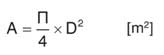
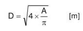
To select the optimal pump, it is necessary to have complete information about the characteristics of the liquid that must be supplied to the consumer. Naturally, a “heavier" liquid will require more energy when pumping a given volume. To describe how much one fluid is “heavier” than another, a concept such as “density” or “specific gravity” is used; this parameter is defined as the mass (weight) per unit volume of the liquid and is usually referred to as “ρ” (the Greek letter “ro”). It is measured in kilograms per cubic meter (kg / m 3). Any liquid at a certain temperature and pressure tends to evaporate (temperature or the boiling point); an increase in pressure causes an increase in temperature and vice versa. Thus, at a lower pressure (even possible under vacuum), which may occur on the suction side of the pump, the liquid will have a lower boiling point. If it is close to or especially below the current temperature of the liquid, steam formation and cavitation in the pump are possible, which in turn can have negative consequences for its characteristics and can cause serious damage (see the chapter on cavitation). The viscosity of the fluid causes friction losses in the pipes. The numerical value of these losses can be obtained from the manufacturer of the particular pump. It should be noted that the viscosity of “thick” liquids, such as oil, decreases with increasing temperature. Water flow It is defined as the volume that must be supplied for the specified time, and is indicated as “Q”. Units of measurement used: as a rule, these are liters per minute (l / min) for low power / capacity pumps, cubic meters per hour (m 3 / h) for medium capacity pumps and, finally, cubic meters per second (m 3 / s) for the most powerful pumps. The dimensions of the cross section of the pipeline are determined by the volume that must be supplied to the consumer at a given fluid flow rate “v”:
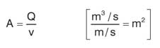
Geodetic (static) suction lift
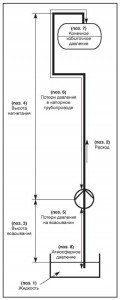
It is defined as the difference in the geodetic level between the pump inlet and the free surface of the liquid in the lowest located reservoir, measured in meters (m) (Fig. 3, Item 1).Static feed height (static head)
It is defined as the difference in the geodetic level between the outlet pipe and the highest point of the hydraulic system to which fluid must be supplied (Fig. 3, item 2).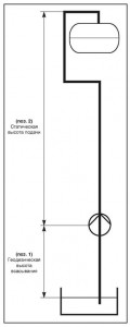
Suction pressure loss
These are friction losses between the liquid and the walls of the pipeline and depend on the viscosity of the liquid, the quality of the surface roughness of the walls of the pipeline and the flow rate of the liquid. With an increase in the flow rate by a factor of 2, the pressure loss increases to the second degree (Fig. 4, item 1). Information on pressure loss in the pipeline, elbows, fittings, etc. at various flow rates can be obtained from the supplier. Pressure losses in the pressure pipe. See the description above (Fig. 4, item 2).Final overpressure
This is the pressure that you must have at the point where the liquid should be supplied (Fig. 5, item 1).Initial Over Pressure
This is the pressure on the free surface of the fluid at the intake site. For an open tank or tank, this is simply atmospheric (barometric) pressure (Fig. 5, item 2).The relationship between pressure and pressure
As can be seen from fig. 6, a column of water with a height of 10 m exerts the same pressure as a column of mercury (Hg) with a height of 0.7335 m. Multiplying the column height (head) by the density of the liquid and the acceleration of gravity (g), we obtain the pressure in newtons per square meter ( N / m 2) or in pascals (Pa). Since this is a very small value, a unit of measurement equal to 100,000 Pa, called a bar, was introduced into the operation of the pumps. The equation in Fig. 6 can be solved in meters of liquid column height:
  Thus, the column height of liquids with different viscosities can be reduced to the equivalent height of the water column. In fig. 7 provides conversion factors for many different pressure units. Below is an example of calculating the total hydraulic head with a pump installation diagram.
  The hydraulic power (P hyd) of the pump determines the volume of fluid supplied at a given pressure for a given time, and can be calculated using the following formula:
Example
A volume of 35 m 3 of water per hour should be pumped from a well 4 m deep into a tank located at a height of 16 m relative to the pump installation level; the final pressure in the tank should be 2 bar. The friction pressure loss in the suction pipe is taken equal to 0.4 m, and in the pressure pipe it is 1.3 m, including knee loss. The density of water is estimated to be 1000 kg / m 3 and the value of the acceleration of gravity 9.81 m / s 2. Solution: Total head (H): Suction head - 4.00 m Suction head loss - 0.40 m Discharge head - 16.00 m Pressure loss in the pressure pipe - 1.30 m Final pressure: - 2 bar * ~ 20 , 40m Minus 1 atm ** ~ -9.87 m Total head - 32.23 m Hydraulic power is determined by the formula: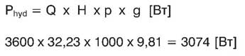 * In this example, the final overpressure is given as absolute pressure, i.e. as pressure measured relative to absolute vacuum. ** If the final overpressure is given as absolute, then the initial overpressure must be subtracted, since this pressure “helps” the pump to absorb liquid.
  Water through the suction pipe of the pump enters the inlet of the impeller and under the influence of rotating blades experiences a positive acceleration. In the diffuser, the kinetic energy of the flow is converted into potential pressure energy. In multi-stage pumps, the cross section of a diffuser with integrated stationary vanes is called a “guide vane”. From the diagram in fig. 10 it can be seen that the potential energy in the form of pressure in the pump grows in the direction from the suction to the discharge pipe, since the hydrodynamic pressure created by the impeller (kinetic energy of the flow velocity) is converted into potential pressure energy in the diffuser.
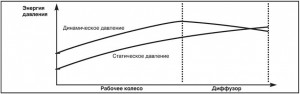
Pump performance
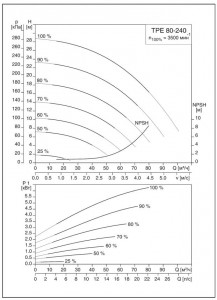
In fig. Figure 11 shows a typical performance of a Q / H centrifugal pump. It can be seen from it that the maximum discharge pressure is reached when the pump flow is zero, i.e. when the pressure port of the pump is closed. As soon as the flow in the pump increases (the volume of pumped fluid increases), the discharge height decreases. The exact characteristic of the dependence of the supply Q on the pressure H is determined by the manufacturer empirically on a test bench. For example (Fig. 11), with a pressure of H 1, the pump will supply a volume of Q 1 and similarly with H 2 - Q 2.
 Pump performance
As already shown above, the friction pressure loss in the pipeline depends on the quality of the surface roughness of the walls of the pipeline, and the square of the fluid flow rate and, of course, on the length of the pipeline. The frictional pressure loss can be represented on the “H / Q” graph as a curve of the hydraulic system characteristic. In the case of closed systems, such as central heating systems, the current discharge height may not be taken into account, since it is balanced by the positive pressure from the side of the suction pipe.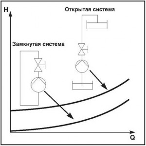
 Pressure loss [Pa / m] at a temperature of t \u003d 60 ° C. Recommended losses in pipes are not more than 150 Pa / m.
 Working point
The operating point is the intersection point of the pump characteristic curve with the hydraulic characteristic curve. It is clear that any changes in the hydraulic system, for example, a change in the flow area of \u200b\u200bthe valve when it is opened or deposits in the pipeline, affect the characteristics of the hydraulic system, as a result of which the position of the operating point changes. Similarly, changes in the pump, such as impeller wear or a change in speed, will cause a new operating point to occur.
Pumps in series
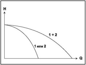
Multistage pumps can be considered as an example of series-connected single-stage pumps. Of course, in this case it is impossible to separate the individual steps, which is sometimes desirable when checking the status of the pump. Since an idle pump creates significant resistance, a bypass line and a check valve must be provided (fig. 14). For sequentially running pumps, the total head (Fig. 15) at any given flow is determined by the sum of the discharge heights of each individual pump.

Pumps in parallel.
Such an installation scheme is used to ensure monitoring of the condition of the pumps or to ensure operational safety when auxiliary or backup equipment is required (for example, twin pumps in a heating system). In this case, it is also necessary to install check valves for each of the pumps in order to prevent the formation of counterflow through one of the inoperative pumps. These requirements in twin pumps are met by a butterfly valve-type switching valve. For parallel running pumps, the total flow (Fig. 17) is defined as the sum of the flow values \u200b\u200bof the individual pumps at constant pressure.
Pump efficiency
The pump efficiency shows how much of the mechanical energy transferred to the pump through its shaft was converted into usable hydraulic energy. Efficiency is affected by:
 - pump casing shape;
- the shape of the impeller and diffuser;
- surface roughness quality;
- sealing gaps between the suction and pressure cavities of the pump.
In order for the consumer to be able to determine the efficiency of the pump at a specific operating point, most manufacturers of pumping equipment attach diagrams with efficiency characteristic diagrams to the pump performance diagrams (Fig. 18).

Typical patterns
Givenfurthertypicallawnumberingdemonstratetheoreticalinfluencediameter ( d ) working wheels on thepressure, feed andconsumedpower. The head is proportional to the diameter in the second degree: According to this pattern, doubling the diameter will increase the pressure by 4 times. The feed is proportional to the diameter in the third degree:
  According to this pattern, doubling the diameter will increase the feed by 8 times. Power consumption is proportional to the diameter to the fifth degree:
  According to this pattern, doubling the diameter will increase power consumption by 32 times.
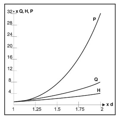
Typicalpatterns
Givenfurthertypicallawnumberingdemonstratethe theoremticalinfluencefrequency rot niya (n) working wheels on thepressure, submissionandconsumedpower. The feed is proportional to the speed: According to this pattern, doubling the speed will double the feed. The head is proportional to the square of the speed:
  According to this pattern, doubling the speed by 8 times will increase the power consumption.
 Consumablepower
P 1 : The power consumed by the electric motor from the mains. For motors directly connected to the pump shaft, as is the case in the circulation pump drive, the maximum power consumption is indicated on the nameplate with the technical data. P 1 can also be determined by the following formula: (3-phase motors) (1-phase motors) where: V \u003d voltage (V) I \u003d current (A) cos ϕ \u003d power factor (-) P 2: power on the motor shaft. In the case where the electric motor and pump are separate units (including standard and submersible motors), the maximum power on the motor shaft is indicated on the nameplate. P 3: Power consumed by the pump The current motor load can be determined from the pump power curve. In case of direct connection of the electric motor to the pump shaft: P 3 \u003d P 2. P 4: Pump power (P hydraulic) The value of the pump power is determined by the formula: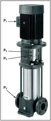
Adaptationpumpsto variablesregimesexploitation
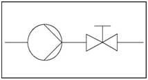
Pressure losses in the hydraulic system are calculated for certain specific operating conditions. In practice, the characteristics of the hydraulic system almost never coincide with the theoretical one due to safety factors laid down in the hydraulic system. The operating point of the hydraulic system with the pump is always the point of intersection of the graph of the characteristics of the pump with the graph of the characteristics of the hydraulic system, therefore, the supply is usually more than is required for a new hydraulic system. Such a mismatch can create problems in the hydraulic system. In heating circuits, noise caused by flow can occur, in condensate systems - cavitation, and in some cases an unreasonably large supply leads to energy loss. As a result, it becomes necessary to shift the operating point (the point of intersection of the graphs of both characteristics) by adjusting the pump and adjusting the hydraulic system. In practice, one of the following methods is used:- Changing the characteristics of the hydraulic system by covering the throttle valve (throttling) (Fig. 22).
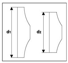
- Changing the characteristics of the pump by reducing the outer diameter (by machining) of its impeller (Fig. 23).
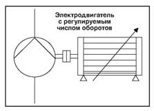
- Change the characteristics of the pump by adjusting the speed (Fig. 24).
Regulationfiling withhelpthrottlevalve
Reducing the orifice of the throttle valve in the hydraulic system causes an increase in pressure loss (hydrodynamic pressure H dyn), making the curve of the hydraulic system curve steeper, as a result of which the operating point shifts towards a lower flow (see Fig. 25). As a result, power consumption is reduced, since centrifugal pumps have a power characteristic that decreases with a decrease in flow. However, power losses during throttle control in a hydraulic system with a high value of power consumption will be significant, therefore, in such cases, special calculations must be performed to assess the profitability of the flow control method using a throttle valve.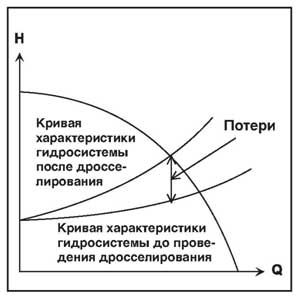
Worker Modificationwheels
In those cases where a decrease in pump performance and pressure is constantly required, the most optimal solution may be to reduce the outer diameter of the impeller. At the same time, either the entire impeller or only the ends of the blades are machined along the outer diameter. The greater the underestimation of the outer diameter, the lower the pump efficiency will become. Decrease in efficiency is usually more significant in those pumps that operate at high speeds. In low-speed pumps, it is not so noticeable, especially if the decrease in the outer diameter is insignificant. When the decrease in the outer diameter is insignificant, then with a fairly high degree of accuracy, you can use the following ratios:
  In fig. 27 shows a method for determining an underestimated diameter D x using a “H / Q” characteristic diagram in linear coordinates. The origin (Q \u003d 0, H \u003d 0) is connected to the new operating point (Q x, H x) by a straight line, continued until it intersects with the characteristic of the existing pump (Q, H) at the point “s”. After that, the new diameter (D x) is calculated by the following formula:
 However, these dependencies are not valid if it is necessary to significantly reduce the performance of the pump. In this case, it is recommended to lower the impeller in several stages. First, the impeller diameter is underestimated to a size slightly higher than the D x value calculated as indicated above. After that, the pump is subjected to tests, after which the final diameter can be determined. In mass production this can be avoided. There are performance graphs for pumps equipped with impellers with different understatement of the outer diameter (see Fig. 28), directly from which the D x value can be calculated using the above formulas.
Frequency regulationrotation
Changing the speed will cause changes in the performance of the centrifugal pump. We will use the typical patterns indicated earlier: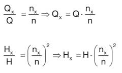
Cavitation
The most common problems during operation of the pumps are related to the suction conditions at the inlet of the hydraulic system and almost always they are caused by too low hydrostatic pressure (back up) at the pump inlet. The reason for this can be rooted in either choosing a pump with parameters that are not optimal for the given operating conditions, or in errors made during the design of the hydraulic system. The rotation of the impeller expels the liquid to the surface of the pump casing, resulting in a vacuum from the side of the suction cavity of the impeller. This causes liquid to suck through the suction valve and piping, which enters the impeller, where it is again thrown to the surface of the pump casing. The vacuum at the pump inlet depends on the difference between the level of the position of the inlet and the surface of the pumped liquid, on the friction pressure loss in the suction valve and the pipeline, and also on the density of the liquid itself. This vacuum is limited by the saturated vapor pressure of the liquid at a given temperature, i.e. pressure at which vapor bubbles will form. Any attempt to reduce the hydrostatic pressure to a value lower than the saturated vapor pressure will cause the liquid to react to this by the formation of vapor bubbles, as it begins to boil. Cavitation in a pump occurs when the pressure on the side of the impeller vanes that faces toward the suction cavity (usually near the pump inlet) drops below the saturated vapor pressure of the liquid, causing gas bubbles to form. Being transferred to the high-pressure region in the impeller, these bubbles are destroyed (explode), and the pressure wave resulting from this can cause damage to the pump (Fig. 31). This damage, which can occur within a few minutes or a few years, is so serious that it can negatively affect not only the pump, but also the electric motor. The most vulnerable parts are bearings, welds and even impeller surfaces. The extent of impeller damage depends on the characteristics of the material from which it is made; for example, the table shows that under the same conditions the damage to the stainless steel impeller is only 5% of the damage caused to the cast iron impeller. Lossinmassvarious materials (in comparison, cast iron \u003d 1.0 is taken as the basis): An increased noise level, pressure drop, and unstable operation are also associated with the phenomenon of cavitation. Often, damage remains undetected until the pump and motor are disassembled.
Calculationsbyeliminatethe dangerscavitation
The cavitational reserve H max of the pump, necessary to eliminate the danger of cavitation, is calculated as follows: H max: Cavitational margin of the pump (see Fig. 33). If he positive, the pump can operate at a given suction height. If he negative, for the pump to work, it is necessary to create conditions under which it becomes positive. H b: Atmospheric pressure on the pump side; this is theoretically the maximum suction lift. This value of H b depends on the density of the liquid and the value of “g” on the pump side (Fig. 32). H fs: The frictional pressure loss in the suction valve and the connected piping also depends on the density of the fluid.
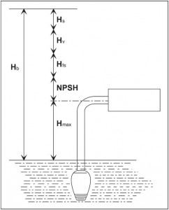
NPSH: Na Positive Suction Head
This parameter reflects the minimum suction pressure required for trouble-free operation. It characterizes the frictional pressure loss in the area from the suction port of the pump to that point of the first impeller at which the pressure is minimal, and determines the hydraulic conditions under which the pump is not able to suck in a solid water column with a height of 10.33 m. Thus, the NPSH value will increase with increasing feed, which can be seen from the characteristics graph in Fig. 35 specific pump. For circulation pumps, the NPSH schedule is not used; instead in fig. 34 is a table showing the minimum suction pressure required at various fluid temperatures. H v: This parameter reflects the saturated vapor pressure of the pumped liquid. It is included in the equation, because at a higher temperature, the liquid begins to evaporate faster. H v also depends on the density of the liquid: H s: This parameter represents the safety margin, which should be determined in specific conditions, depending on the degree of reliability and reliability of the calculation methodology used. In practice, it is taken equal to 0.5-1 m. In the case of the presence of gas in water, this value is often chosen equal to 2 m.
howto avoidcavitation
This argument is based on the above formula: H max \u003d H b - H fs - NPSH - H v - H s and takes into account the influence of each member of the equation. H max: The pump must always be installed as low as possible or it is necessary to raise the liquid level on the suction side. The latter method is often the cheapest solution. The positive suction pressure generated by the pump (if any) or the expansion tank must be kept as high as possible. H b: This indicator is constant when pumping a certain liquid in a given place. H fs: The suction pipe must be as short as possible and have a minimum number of elbows, valves, valves and fittings. Npsh: Select the pump with the lowest NPSH required. H v: This parameter may decrease when the temperature of the liquid drops (ambient temperature). H s: Installed individually. The easiest way to avoid cavitation is to reduce the pump flow by partially closing the discharge (or pressure) valve; as a result, the required value of NPSH and H fs will decrease, therefore, the value of H max will increase.Alternativemethodologycalculationforeliminatethe dangerscavitation
Many people prefer to convert the formula to NPSH functions as follows: This gives the available NPSH value for this hydraulic system, which can then be compared with the required NPSH required value indicated on the performance graphs of the corresponding pump. Thus, if NPSH available ≥NPSH required cavitation can be avoided. However, if NPSH available ≤NPSH required then the risk of cavitation remains.
 Connectionelectric motor "GRUNDFOS» inaccording to the designation on its nameplate
Decryptiondesignations: “ - “Means“ from - to “; “ / “Means that the electric motor can be connected in two different ways; “ D“Designation of the connection of the motor windings according to the triangle pattern; “ Y“Designation of the connection of the motor windings according to the" star "scheme. 1 x 220-230 / 240 V- The motor can be connected to a single-phase AC network with a voltage of U \u003d 1 x 220-230V.
- The motor can be connected to a single-phase AC network with a voltage of U \u003d 1 x 240V.
 3
x220
–
240D / 380–
415Y V
3
x220
–
240D / 380–
415Y V
- The motor can be connected to a three-phase AC network with a voltage of U \u003d 3 x 380-415V according to the "star" scheme.
- The motor can be connected to a three-phase AC network with a voltage of U \u003d 3 x 220-240V according to the "triangle" scheme (for example, in Belgium, Norway, Italy, France).
- The motor can be connected to a three-phase AC network with a voltage of U \u003d 3 x 220-240V according to the "star-delta" scheme.
 3
x380
–
415D V
3
x380
–
415D V
- The motor can be connected to a three-phase AC network with a voltage of U \u003d 3 x 380-415V according to the "triangle" scheme.
- The motor can be connected to a three-phase AC network with a voltage of U \u003d 3 x 380-415V according to the "star-delta" scheme.
Along with productivity, the pressure of the pump is its most important characteristic. We understand what it means, and also disclose the main ways of regulating the pressure of the pumps ...
Pump pressure(head) - along with pump feed, another key characteristic of the pump. Shows the height to which the unit is able to lift the column of pumped fluid. It depends on what kind of energy each particle of the liquid acquires in contact with the working body of the pump. The range of this characteristic ranges from 2-3 meters for small pumps and up to 1800 meters (about 180 atmospheres) for industrial pumps.
Pressure of various types of pumps
Pressure depends on the type of pump. For example, centrifugal single-stage pumps are not able to lift water to a height of more than 100-110 meters even with a very large electric motor power. But vortex pumps provide pressure up to 160 meters even at low power due to the special shape of the impeller. Each particle of water comes into contact with such a wheel several times and gains more energy. The reverse side of such a “profitable” is a significant deterioration in such a characteristic of a vortex pump as its supply. Another possible solution to improve the pump head is to use several successive centrifugal wheels in the housing of one pump. Such units are called pressure boosting pumps. Their efficiency compared to vortex is quite high. Very high pressure characteristics are provided by so-called positive displacement pumps. These include, for example, gear or piston pumps.
Ways to regulate pump pressure
The pump pressure can be adjusted using a frequency converter (pressure decreases at the same time as the supply). This method of regulating pressure is the most economically feasible, because it allows the pump to work without a significant decrease in efficiency, despite a decrease in flow. As a rule, a strong drop in efficiency occurs only with a very sharp (less than 30% of the nominal) decrease in speed. Another way to control the pressure by reducing the speed of the pump shaft is to use a gearbox, but this leads to a sharp decrease in the efficiency of the unit.
Throttling is a method of reducing pressure by reducing the cross section of the pressure line (after the pump) or suction line (before the pump) using a valve, shutter or valve. Reducing the cross section of the pressure line dramatically reduces the efficiency of the pump, since the pump continues to operate at full capacity, and part of its pressure is uselessly extinguished at the point of decreasing cross section of the line. Reducing the cross-section of the suction line does not reduce the efficiency so much, but creates an additional vacuum at the pump inlet, which can lead to cavitation.
Bypassing - (by pass - bypassing) - a method of regulating the flow and pressure of the pump. It consists in installing an adjustable or unregulated bypass (bypass) from the pressure line to the suction. In relation to the pump, this is similar to a decrease in resistance, i.e. there is a decrease in pressure. In relation to the consumer network, this is similar to a decrease in supply. As a result, the operating point (Q-H) will shift abruptly downward, i.e. it is possible to obtain at the same time a smaller head and a smaller supply in the consumer network (the energy of the liquid goes to discharge). Bypassing dramatically reduces the efficiency of the pump unit.
How to choose the pump with the right pressure?
There, select the type of equipment "pump". Indicate the required pressure in m.v.st. (meters of water). If necessary, select other pump parameters, for example, capacity, type of pump, principle of operation. Press the “select” button, and after a few seconds you will be taken to the selection results page. The program will show you all the pump models that match the requested specifications.
Many very vaguely represent the practical work of one type or another of pumps, depending on their classification. But this case is completely solvable if you look at the articles located in the subsection of the website of the online hypermarketwebsite “Articles” that specifically describe on what principle these or those types of pumps work: “Classification of pumps according to their design"," Pump. Volumetric pumps ”,“ Pump. Dynamic pumps (continued). ”
Now let's try to tell what pressure is created by the pump. In practice, we will explain what pressure is, which can create an aggregate at the output and what it affects.
What is the pressure and pressure that a pump can create
During its operation, the pump creates an increase in the specific energy of the liquid, which it pumps, in other words, potential energy, relative to 1 kg of water mass.
Its full value for the total volume of the solution at the inlet to the unit depends on the inlet section of the receiver pipeline “S1”, the specific flux density “p”, and the flow rate “v”. Then, if we take the cross-section as the center of the cross-section of the pipeline Z1, the specific energy formula at the pump inlet: E1 \u003d Z1g + p1 / q + v12 / 2.
Now we derive the formula for the specific energy of the flow at the pump outlet when the section of the pipeline S2, then with the same data, as for section 1-1 we get: E2 \u003d Z2g + p2 / q + v22 / 2, accordingly, it is easy to calculate the increase in flow energy during pump operation:
E2 - E1 \u003d p / q \u003d (Z2 - Z1) g + (p2 - p1) / q + (v22 - v12) / 2 and here we get the pump pressure formula "P": p \u003d (Z2 - Z1) gq + (p2 - p1) + q (v22 - v12) / 2
Now we can show the formula from the concept of "fluid pressure" in each section of the pipe (at the inlet to the pump and at the outlet of it): H \u003d (Z2 - Z1) + (p2 - p1) / qg + (v22 - v12) / 2g.
If you believe this formula, then the pressure capabilities of the pump consist of the total pressure gauge + the difference of the squares of the liquid flow velocities in the suction and pressure pipes of the unit.
Pump designers calculate the pressure head of the future unit according to the formula:
H \u003d Ng.v. + Ng.n. + h.p. + h.p ., where already Ng.v and Ng.n are the geometric heights of the corresponding pipes - suction and discharge, and h.p. and hпн - pressure loss in the corresponding pipelines - suction and pressure (discharge).
This shows that the pressure that the pump can develop is equal to the total geometric heights of the suction and discharge pipes + the total value of the fluid pressure loss when it moves from the receiving tank (tank) to the place where the jet flows from the discharge main pipe.
Practical use of the pump's ability to create a certain pressure, pressure
In practice, when we choose a pump, we immediately pay attention to what height it can raise a column of water of a certain pressure, so that we know approximatelythe unit will be able to deliver water to the supply taps on the second (approximately) floor of your autonomous home. Or how the pump can cope with raising water from a well 100 meters deep.
We have all seen such graphs in the operating instructions of a pump for a long time and did not want to understand that they depict the process of changing the pump head depending on, for example, performance.
It turns out that the more water the pump discharges into the discharge pipe, the lower the pressure of the water jet will be with open flow taps. The pressure can be measured at the outlet of the pump, and with an increase in the height of the water supply (as well as with an increase in the length of horizontal sections), the pressure from the pump will be proportionally reduced by a certain amount.
If even without special calculations, if possible, the pump parameters to create a certain pressure at the outlet (pressure in meters of the water supply height) do not match your desires, and if there is no other way to conduct the line in your particular case, try using intermediate pressure boosting pumps in the water line or buy several pumps for different purposes, which in the total work will help provide your home and the whole household with life-giving moisture.