Fuel supply adjustment fuel pump YamZ 236. Maintenance of fuel equipment
The first stage of the repair of the fuel pump, the adjustment of the fuel pump YaMZ 238, must be performed on special equipment. It is important to identify the possible causes of failure, to determine the degree of wear of parts.
Quality adjustment affects the economy and efficiency of diesel engines. Affects the operation of the fuel system.
Features of adjustment of TNVD YaMZ 7511
Begin the adjustment by checking the settings. Diagnose the condition of the valves and their pressure.
Fuel is fed to the pump head. If the fuel leaks noticeably in the first minutes of the test, replace the discharge valve. In the absence of leakage from the fittings, the pressure is increased. Carefully observe at what point the valve opens.
If the pressure is not set when fuel enters the tube, the pressure springs of the pressure valves are replaced.
Also, when adjusting the fuel injection pump YaMZ 7511, check the angle of the start of fuel injection. Use a momentoscope. The measured angle must correspond to the values \u200b\u200bfrom the manufacturer's table.
Working adjustments of the drive TNVD YaMZ 236
The minimum and maximum speeds are adjusted with the appropriate bolts. The spring preload is set using a screw.
Nominal flow is regulated by a bolt. Turns of the start of operation are adjusted by the corrector body. Bolt limit the maximum speed.
In the process of adjusting the drive fuel injection pump YaMZ 236 determine the time of the end of the extension of the rack. In case of deviations, the required number of revolutions is set by the screws of the two-arm lever.
The adjustment of the fuel injection pump for trucks is carried out at the stand with precision accuracy. Perform:
- Checking the nominal value of the fuel supply;
- Rail travel adjustment;
- Set the value of the fuel supply during overloads and at startup.
After the pump has been fully adjusted, tests and break-in are performed. The amount of fuel leaking through the gaps is measured. Only slight leaks are allowed. If there is a noticeable fuel leak, the elements are checked for leaks.

During the tests, in accordance with the video adjustment of the fuel pump YaMZ 238, possible deviations in the operation of the pump are established. Noises, jamming of parts, leak in the places of seals are eliminated.
During operation, the moment and amount of fuel supply is violated. The angle of advance of injection changes.
To maintain the pump in working condition, it is recommended that after every 800 hours of operation, remove the element, check and adjust the fuel injection pump YaMZ 238, as well as other elements of the mechanism.
Before adjustment, Dp-11 diesel oil in accordance with GOST 5304-54 is poured into the pump casing and in the casing of the regulator to the upper marks of the level gauges and the tightness of the discharge valves is checked by crimping them with filtered diesel fuel through the pump inlet channel under a pressure of 1.7-2.0 kgf / cm2 with the rack position corresponding to the switched off feed. Fuel leakage from connecting nipples within 2 minutes is not allowed. The hole in the bypass valve housing is closed with a screw plug during adjustment. The fuel start is checked and adjusted without an automatic injection advance clutch. The moment of fuel supply start is most accurately determined by the beginning of the fuel outflow from a segment of the high pressure pipe (mounted on the nozzle) when the fuel pressure in the pump head is at least 22 kgf / cm2. If it is not possible to use this method, it is recommended that the start of fuel supply be determined by the start of fuel movement in the momentoscope. A diagram of the device of the momentoscope is shown in Fig. 81. The beginning of fuel supply in sections is determined by the angle of rotation of the cam shaft of the pump when it is rotated clockwise, when viewed from the side of the drive. The first section of a properly adjusted pump starts to supply fuel 37-38 ° to the axis of symmetry of the cam profile. To determine the axis of symmetry of the cam profile, it is necessary to fix on the dial the moment the fuel starts to start when turning the cam shaft clockwise, turn the shaft clockwise by 90 ° and fix on the dial the moment when the fuel starts to start when turning the shaft counterclockwise. The middle between two fixed points defines the axis of symmetry of the cam profile. The limb must be tightly connected to the drive shaft. When turning the limb, play between the shaft and the limb is not allowed. If the angle at which the first section of the pump begins to supply fuel is conventionally taken as 0 °, then the remaining sections should begin to supply fuel at the following values \u200b\u200bof the rotation angles of the cam shaft:


When installing additional washers, the preload of the corrector spring increases, and the cyclic feed increases, when removing the washers, the cyclic feed decreases. The value of the starting fuel supply at 70-90 rpm of the camshaft should be for pumps equipped with new plunger pairs and pressure valves, 220-240 mm3 / cycle, for pumps that have been overhauled and equipped with plunger pairs and pressure valves that were in operation not less than 200 mm3 / cycle. The maximum permissible starting fuel supply in operation should not be less than 180 mm3 / cycle. The adjustment is made by unscrewing the screw 21 (see. Fig. 73) the wings. After that, the backstage screw must be locked by chasing.
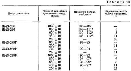
The screw adjusting the nominal feed set the slide rail corresponding to the cyclic feed sections in the range specified in the table. 23, with the stop of the control lever of the regulator against the maximum speed limit bolt.
Then check the unevenness of the fuel supply by the pump sections with a partial average cyclic feed of 15-20 mm3 / cycle at 240-260 rpm of the cam shaft. Uneven fuel supply by pump sections should not exceed: when equipped with new plunger pairs and valves for the YaMZ-236 engine pump, -40%, for YaMZ-238 engine pumps of all modifications, 50%; when equipped with plunger pairs and valves that were in operation, for the YaMZ-236 engine pump - 60%; for pumps of YaMZ-238 engines of all modifications - 70%.
In the case of large non-uniformity of supply, it is necessary to bring it to acceptable values \u200b\u200bby rearranging or replacing the discharge valves, as well as the selection of pressure valve springs.
Further, with bolt 12 (see Fig. 82), the maximum speed limits set the beginning and end of the extension of the rail. The beginning of the extension of the rail of pumps of the YaMZ-236, YaMZ-238, YaMZ-238A and YaMZ-238K engines should be at 1070-1080 rpm of the cam shaft, the end of the extension - 1120-1150 rpm, for the pumps of the YaMZ-238G engine the start of the extension - at 870-880 rpm, end at 930-980 rpm, for the YaMZ-238I engine pump, the start of extension at 780-790 rpm. The number of revolutions of the camshaft of the YaMZ-238I engine pump corresponding to the end of the rack extension (complete shutdown by the fuel supply regulator by the pump sections through the nozzles) should be 30-55 rpm higher than the number of turns of the rack extension when the regulator control lever rests against the maximum restriction bolt revolutions. In case of deviation of the number of revolutions of the end of the extension from the set, the screw 10 of the two shoulders of the lever is adjusted. When screwing in the screw, the number of revolutions of the end put forward the rails decreases, when screwing out it increases.
After this, it is necessary to check, with the bolt turned out, 13 minimum idle turns, that the fuel supply automatically shuts off at 225-275 rpm of the cam shaft of the pump.
Acceptance tests of the adjusted pump are carried out with a set of nozzles designed to break in the pump for 45 minutes at 1020-1040 rpm of the cam shaft. The regulator control lever should rest against the maximum speed limit bolt. During the tests, the amount of fuel leaked through the gaps in the precision parts into the cavity of the cam shaft of the fuel is measured. The maximum permissible leakage of fuel into the cavity of the camshaft for 20 minutes should not exceed 4.5 cm3 for new precision assemblies for YaMZ-236 engine pumps and 7.0 cm3 for previously used precision assemblies; for pumps of YaMZ-238 engines of all modifications - no more than 6.0 cm3 for new precision units n 9.0 cm3 for precision units that were in operation. In the case of a sharp increase in leakage, it is necessary to check the tightness of the connection between the ends of the plunger bushings and the pump housing and to eliminate the defect. During the acceptance tests, the fuel supply through the nozzles is turned off with the regulator control lever in the middle position. Fuel injection through nozzles is not allowed. When you turn the bracket 1 backstage 45 ° from the starting position, the fuel supply in all sections should completely stop. Abnormal noises, jamming of plungers and other parts (at different positions of the rail), fogging and leakage in the places of seals are not allowed. Before removing the pump from the stand, the openings of the fuel outlet and supply are closed with traffic jams and caps; an automatic injection advance coupling is installed on the pump.
With proper and regular maintenance, the fuel equipment of the engine can work for a long time without repair.
Service fuel equipment with utmost care and cleanliness. After disconnecting the fuel lines, the fittings of the fuel and booster pumps, nozzles, filters and openings
protect pipelines from dirt by plugs, caps, plugs or clean insulation tape. Before assembly, thoroughly clean all parts and rinse with clean gasoline or diesel fuel.
When disconnecting the high pressure fuel line from the nozzle, hold the nozzle nozzle with a wrench to prevent it from loosening and fuel leakage. After disconnecting, check the tightness of the fitting without removing the engine nozzle. Installation and fastening of high-pressure pipelines and the drainage system piping to the nozzles is carried out after installing the nozzle and tightening the bracket nut.
In order to prevent “spacing” of the engine during the winter period of operation, it is strictly forbidden to pour over the high pressure fuel pump before starting hot water. During the entire period of operation, it is forbidden to wash the fuel pump with water under pressure.
When the engine is stopped during the winter period of operation, the bracket for the backstage of the regulator should be left in the off position.
Nozzle maintenance
During servicing, adjust each nozzle to an injection start pressure of 16.5 +1.5 MPa (165 +15 kgf / cm 2).
Adjustment is recommended to be carried out on a special device of the type KI-3333 or similar in design. The injection start pressure is regulated by a screw with the nozzle cap removed and the lock nut unscrewed (Fig. 68). When the screw is screwed in, the pressure rises, when screwed out, it decreases. After long-term operation on the engine, the injection pressure can be reduced to 15 MPa (150 kgf / cm 2).
Spraying quality is considered satisfactory if, when fuel is injected into the nozzle at a speed of 70-80 strokes per minute, it is injected into the atmosphere in a foggy state and is evenly distributed over the cross section of the jet cone and at each nozzle opening. The start and end of the injection should be clear. Fuel injection for new injectors
which is accompanied by a characteristic sharp sound. The absence of a sharp sound in the used nozzles when checking them on a manual stand does not serve as a criterion that determines the poor quality of the nozzle. In case of coking of one or several holes, disassemble the nozzle, clean its parts and rinse with gasoline. When leaking on a cone or sticking a needle, replace the spray gun. The body of the spray gun and the needle make up a precision pair in which the replacement of one part is not allowed.
Fig. 68. Nozzle needle lift pressure adjustment
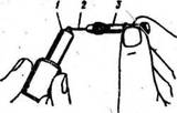
Fig. 69. Cleaning nozzle openings:
1 - spray; 2 - steel wire; 3 - chuck
Disassemble the nozzle in the following sequence:
Unscrew the nozzle cap;
Unscrew the lock nut and turn the adjusting screw all the way;
Unscrew the spring nut one and a half to two turns;
Unscrew the nut of the spray gun;
Remove sprayer to prevent sprayer needle from falling out.
To prevent breakage of the fixing pinsdo not remove spray gun nut without first unscrewingvariable adjustment screw and spring nut.
The sprayer must be cleaned from the outside using a wooden block soaked with diesel oil, rinse the internal cavities in gasoline, clean the nozzle holes with a 0.3 mm diameter steel wire (Fig. 69). Do not use sharp or hard objects or sandpaper to clean the spray gun.
Before assembly, thoroughly rinse the spray gun and needle in clean gasoline and lubricate with filtered diesel fuel. After that, the needle, extended by one third of its length from the atomizer body, should tilt the atomizer at an angle of 45 ° smoothly, without delay, should completely lower under the action of its own weight.
When tightening the nut, rotate the spray gun against the direction of screwing the nut all the way into the fixing pins and, holding it in this position, screw the nut by hand, then tighten the nut completely.
The tightening torque of the atomizer nut is 70-80 N m (7-8 kgf-m) of nozzle nozzle - 80-100 N m (8-10 kgf-m).
After assembling the nozzle, adjust the pressure at the beginning of injection and check the quality of fuel cutting and the accuracy of the sprayer.
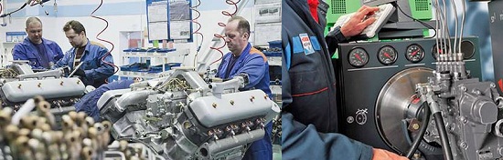
High Pressure Fuel Pump Service
Maintenance of the high pressure fuel pump should be performed by qualified workers in a workshop with special stands.
It is recommended to regulate fuel pumps at the stands NC-10L and NC-108 manufactured by the Motorpal enterprise of Czechoslovakia, at the MD-12 stands of the Mir-koz enterprise of Hungary, A1027 of the Austrian company Friedmann & Maier ”and others similar in design.
The stand must be equipped with:
- a mechanism that provides a stepless change in the frequency of rotation of the drive shaft in the range from 0 to 1500 rpm;
- a device for installing and securing the test pump assembly with a speed controller, an automatic fuel injection timing clutch and a booster pump;
- fuel tank, coarse and fine fuel filters;
- a fuel system that provides fuel pressure in the pump head up to 2.3 MPa (23 kgf / cm 2);
- a device for measuring and selecting portions of fuel supplied by each section of the high pressure fuel pump;
- a device for heating fuel and maintaining its temperature in the range of 35 ° ± 2 ° C;
- a totalizing counter of the number of strokes of the plunger, interlocked with a device for measuring and selecting portions of fuel;
- tachometer for setting speed mode; i) a dial for adjusting the alternation of flows between sections of the pump;
- flywheel on the pump drive shaft with a momentinertia not less than 0.17 kgf-m 2 (1.7 kgf cm sec 2);
- the required number of pressure gauges, vacuummeters and pipelines.
Separate adjustment and verification of the parameters of the high-pressure fuel pump is allowed, using specially made stands equipped with the above-mentioned devices necessary for this purpose. Technical requirements for the equipment of the stand are given in Appendix 3.
Before installing the pump on a bench, check the axial play of the cam shaft. If the backlash exceeds 0.1 mm - adjust it with shims within 0.01-0.07 mm.
Adjust the pump with a set of tested injectors secured to the sections. Install nozzles on the engine in the order they are secured to the pump sections.
When checking the high pressure fuel pump, first check the start of the fuel supply by the pump sections, then the size and uniformity of the fuel supply.
Fuel startcheck and adjust without injection advance clutch at the start of fuel movement in the momentoscope. The beginning of fuel injection by the first section of the pump is determined by the rise of the plunger of the first section of the fuel pump when the cam shaft rotates clockwise, as viewed from the drive end. The first section of a properly adjusted pump starts to pump fuel when the plunger is raised by 4.50 ± 0.05 mm; control by indicator with a division price of 0.01 mm.
If the angle at which the 1st section begins to supply fuel is conventionally taken as 0 °, then the others should start supplying fuel in the following order.
For the engine pump YaMZ-236M:
section No. 1-0 ° of rotation of the cam shaft;
"No. 4-45 °"
"No. 2-120 °"
"No. 5-165 °"
"No. 3-240 °"
"No. 6-285 °"
For the engine pump YaMZ-238M:
section No. 1-0 ° of rotation of the cam shaft:
"No. 3-45 °"
"No. 6-90 °"
"No. 2-135 °"
"No. 4-180 °"
"No. 5-225 °"
"No. 7-270 °"

Fig. 70 Turning out a bolt of a pusher
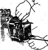
Fig. 71. Adjusting the minimum speed
The inaccuracy of the interval between the start of fuel supply by any section of the pump relative to the first is not more than 0 ° 20 ".
Start the fuel supply by adjusting the pusher bolt (Fig. 70), when unscrewing which the fuel begins to be supplied earlier, when screwing in - later. After adjustment, lock adjusting bolts with nuts.
The size and uniformity of the fuel supply by sections of the high pressure pump shall be regulated together with a set of nozzles and fuel lines of high pressure with a length of 415 ± 3 mm. The volume of the internal cavity of each high pressure fuel line should be 1.3 ± 0.1 cm 3 and is determined by the method of filling with fuel.
The sequence of checking and adjusting the size and uniformity of the feed:
Check the fuel pressure in the line at the inlet to the high pressure pump. The pressure should be in the range of 50-100 kPa (0.5-1 kgf / cm 2) at 1050 rpm of the cam shaft. If the pressure is greater or less, unscrew the bypass valve plug and adjust the opening pressure under the bur of the number of shims.
Check the tightness of the discharge valves. In the position of the rail corresponding to the switched off supply, the discharge valves must not allow fuel to pass through under pressure of 170-200 kPa (1.7-2 kgf / cm 2) for 2 minutes. In the event of a leak, replace the discharge valve.
When the control lever rests against the minimum speed bolt, check and, if necessary, adjust the speed corresponding to full automatic shutdown by the fuel supply regulator within 225-275 rpm. When the minimum speed screw (Fig. 71) and the buffer spring housing (Fig. 72) are turned out, the revolutions decrease.
When the control lever rests against the maximum speed limit bolt, check the speed of the cam shaft of the pump corresponding to the start of the rail ejection (the beginning of the rail movement in the direction of turning off the feed).

Fig. 72. Unscrewing the buffer spring housing
The start of the ejection should be:
for engines YaMZ-236M, YaMZ-238M, YaMZ-238AM YaMZ-238VM and YaMZ-238KM - at 1085 ± 10 rpm of the cam shaft;
for the YaMZ-238GM \u200b\u200bengine - at 875 ± 10 rpm;
for the YaMZ-238IM engine - at 785 ± 10 rpm.
If necessary, adjust the speed with the maximum speed limiter bolt (Fig. 73).
When the control lever rests against the maximum speed limit bolt, check the speed of the cam shaft of the pump corresponding to the end of the rail ejection (complete shutdown of the feed). The end of the ejection should be:
for engines YaMZ-236M, YaMZ-238M, YaMZ-238AM, YaMZ-238VM and YaMZ-238KM at 1135-1165 rpm of the pump cam shaft;
for the YaMZ-238GM \u200b\u200bengine - at 930-980 rpm of the cam shaft;
for the YaMZ-238IM engine, the rotation frequency of the end of the ejection of the rack (complete shutdown of the feed) should be 30-55 rpm higher than the beginning of the ejection of the rack.
Fig. 73. Adjusting the maximum speed
In case of deviation from the set value, unseal and remove the cover / (Fig. 74) of the inspection hatch of the regulator, keeping the position of the adjusting screw unchanged 3.
Fig. 74. Speed \u200b\u200bcontroller:
1 - inspection hatch cover: 2 - regulator bracket; 3 - adjusting screw
Turn the end of the ejection rod as follows:
a) changing the position of the screw / (Fig. 75) of the two shoulders lever, install with a bolt 5 restrictions on the maximum rotation speed of the beginning of the ejection of the rack at Yu85 ± 10 rpm (875 ± 10 rpm for YaMZ-238GM \u200b\u200band 785 ± 10 rpm for YaMZ-238IM) of the pump cam shaft;
Fig. 75. The speed controller with the cover of the inspection door removed:
1 - double shoulder lever screw: 2 - screw adjusting the nominal feed; 3 - adjustment of the magnitude of the starting feed screw backstage; 4 - minimum speed limit bolt: 5 - a bolt of restriction of the maximum frequency of rotation; 6 - control lever
b) check the speed of the end of the ejection of the rack and, if necessary, adjust it.
When the two-arm lever screw is screwed in, the frequency of rotation of the end of the ejection of the rack decreases; when twisted - increases.
When the control lever rests against the maximum speed limit bolt, check the performance of the pump sections. The fuel supply by each section of the pump must be within the limits indicated in table 5..
Table 5
Adjust the fuel supply by each section of the pump by shifting the rotary sleeve relative to the gear sector, for this, unscrew the clamping screw of the corresponding gear sector (Fig. 76). When turning the sleeve relative to the sector to the left, the supply decreases, to the right it increases (Fig. 77). After adjustment, check the tightness of the clamping screws.
For YaMZ-236M, YaMZ-238M and YaMZ-238AM engines with regulators equipped with a reverse corrector assembly, check the fuel supply at 500 rpm of the cam shaft of the pump and when the control lever stops against the maximum speed screw. The feed should be 86-91 mm 3 per cycle for the YaMZ-236M, YaMZ-238M engines, for the YaMZ-238AM engine - 79-84 mm 3 per cycle. If the fuel supply is less than specified, use a special socket wrench to turn out a stopper 29 (fig. 24a), remove the spring 28 corrector, emphasis 30 and shims between the stop and the bush 31, increase their number using special adjusting washers with a thickness of 0.05 mm, 0.2 and 0.4 mm. A 0.05 mm thick washer changes the fuel supply by about 5 mm 3, 0.2 mm by 20 mm 3 and 0.4 by 40 mm 3 per cycle. If the fuel supply is greater than indicated, the thickness of the washer package should be reduced.
Assemble the reverse corrector, for which insert the emphasis 30 with adjusting washers on the sleeve side 31 corrector, spring 28 with cork 29. Wrap the plug with a special socket wrench and check the fuel supply at 500 rpm of the cam shaft.
Check the power reserve of the staff. The power reserve of the rack means the value of the free run of the rack at 450 rpm and with the stop of the control lever in the bolt of limiting the minimum speed. The power reserve of the rail should be at least 1.0 mm. The power reserve of the rail is regulated by the adjusting screw. 3 (Fig. 74). When screwing in 3 the power reserve of the rail decreases, when unscrewing it increases. If the change in position is backstage 2 (fig. 24) when the adjusting screw is loosened, the rocker screw prevents 3 (Fig. 75), unscrew it so that the emphasis of the link is maintained through the adjustment screw 3 (Fig. 74). Please note: the protrusion of the backstage screw beyond the outer end of the regulator cover is not permissible.
After completing the adjustment, lock the adjusting screw with a nut, and check the backstage screw.
Fig. 76. Unscrew the coupling screw of the gear sector
Fig. 77. Adjusting the amount of fuel supply
Check once again that there is a complete shutdown of the feed according to claim 5. If there is no shutdown of the feed, reduce the value of the starting feed to 220 mm 3 / cycle by shifting the rotary bushings of all sections (Fig. 77), then restore the nominal fuel supply indicated in the table. 5, the screw for adjusting the nominal supply (Fig. 78). With the rotary bushings of the sections, adjust the evenness of the nominal feed rate in the sections (item 6).

Fig. 78. Adjusting the performance of the pump sections
Check the frequency of rotation of the start of the reverse corrector. It is understood as such a rotation speed from which, when the speed is reduced, a systematic decrease in fuel supply begins.
If the speed decreases, at which the inverse corrector starts to operate, the plug must be removed with a special socket key 29 (Fig. 24) and add the required number of shims between the spring 28 and cork 29, using the same adjusting washers as when adjusting the feed at 500 rpm. A 0.05 mm thick washer changes the frequency of rotation of the start of operation by about 25 rpm, 0.2 mm by 100 rpm, 0.4 mm by 200 rpm Wrap the plug 29 and again check the speed at which the inverse corrector starts. If the start of operation occurs at a higher speed than 770 ± 20 rpm, it is necessary to reduce the thickness of the set of shims accordingly.
For pumps of YaMZ-238VM and YaMZ-238KM engines, check the presence of an increment of the cyclic feed by 3-6 mm 3 / cycle at 770 ± 20 rpm of the cam shaft compared to the nominal feed at 1030 ± 10 rpm. If necessary, adjust the required increment by the corrector body. When screwing in the corrector housing, the feed increases, when screwing out, it decreases. After adjustment, the corrector housing must be securely locked.
Check the amount of starting fuel supply, which should be at least 220 mm 3 per cycle at 80 ± 10 rpm of the cam shaft of the pump. Adjust with the adjusting screw. 3 (Fig. 75) the scenes only in the direction of increasing the fuel supply, then lock the screw. After the adjustment, check and, if necessary, adjust the performance of the pump sections with the nominal flow adjustment screw (Fig. 78).
Check the fuel shutdown with the regulator bracket. When the bracket is rotated to the lower position by 45 °, the fuel supply by all sections of the pump should completely stop. If the feed does not turn off, then check the ease of movement and eliminate possible jamming of the rail.
Seal the high pressure fuel pump and regulator.
Install the injection advance clutch and tighten the nut of its fastening with a torque of 100-120 N m (10-12 kgf-m). Tighten the nut of the timing advance coupling in all cases when the high pressure pump is removed from the engine.
If necessary, add oil to the injection advance clutch.
ROTATION REGULATOR
Figure 30 - Speed \u200b\u200bcontroller
1-boost fuel boost corrector; 2-axis two shoulders lever; 3-cover inspection hatch; 4-spring regulator; 5-shouldered lever; 6-spring rack lever; 7-screw two shoulders lever; 8-buffer spring; 9-case buffer spring; 10-adjusting bolt; 11-spring lever shaft; 12-negative corrector; 13-body spring corrector; 14-spring negative corrector; 15-clip backstage; 16-sleeve negative corrector; 17-lever regulator; 18-lever negative corrector; 19-screw power adjustment; 20-lever rack; 21-stage 22-fifth; 23 - cargo coupling; 24-loads regulator; 25-holder of goods; 26-axis cargo; 27-pinion gear; 28-crackers; 29-roller load holder; 30-cup; 31-lever spring 32-rod rack; 33 rail 34-point
The speed controller 5 (Fig. 28) is a direct-acting mechanical all-mode regulator with an overdrive to the load drive, designed to maintain the engine speed set by the driver by automatically changing the amount of fuel supplied depending on the change in engine load. In addition, the controller limits the maximum engine speed and ensures that the engine is idling. The regulator has a device to turn off the fuel supply at any time, regardless of the engine operating mode. Automatically maintaining high-speed operation under changing loads, the regulator provides economical operation of the engine. The device of the speed controller is shown in Fig. thirty.
The regulator is located at the rear end of the high pressure fuel pump. On the cone of the cam shaft is a blowing gear 27 with a damping device. Rotation from the pump shaft to the drive gear is transmitted through rubber crackers 28. The driven gear is made integrally with the roller 29 of the cargo holder and mounted on two bearings in the cup 30.
A load holder 25 is pressed onto the roller (Fig. 30), on the axes 26 of which there are loads 24. The weights with their rollers abut against the end face of the coupling 23, which, through the thrust bearing and the heel 22, transfers the load force to the regulator lever 17, suspended together with the two-arm lever 5 on common axis 2.
The clutch 23 with the persistent fifth 22 assembly at one end rests on the guide surface of the holder, and for the second end is suspended on the lever 18 of the negative corrector, mounted on the sleeve 16 of the negative corrector. The fifth of the cargo coupling is connected through the negative corrector assembly to the rail lever 20 and through the rod 32 to the fuel pump rail. To the top of the rack lever is attached a spring 6 of the rack lever, which holds the pump rack in a position corresponding to the maximum flow rate, which provides an increased fuel supply when starting the engine. A finger is pressed into the lower part of the rail lever, which enters the hole of the backstage slider 21. The shaft 11 of the regulator lever is rigidly connected to the control lever 6 (Fig. 28) and the spring lever 31 (Fig. 30). The movement of the regulator control lever is limited by two bolts 4 and 7 (Fig. 28). For the spring lever 31 (short hook) (Fig. 30) and two shoulders lever 5 (long hook), the regulator spring 4 is hooked, the force of which is transmitted from the two shoulders lever to the regulator lever through the screw - 7 of the two shoulders lever. An adjusting bolt 10 is screwed into the regulator lever, which abuts against the spring lever shaft and serves to adjust the nominal fuel supply. In the lower part of the regulator lever there is a correction device (12, 13, 14, 16, 18) with a negative corrector, designed to form the external high-speed characteristic of the high-pressure fuel pump and the engine torque.
The lever of the regulator is equipped with a side pad that holds the sleeve 16 of the inverse corrector and the thrust heel 22 from turning. In addition, the shank of the bolt securing the side plate, entering the lateral longitudinal groove of the sleeve prevents it from falling out of the lever bore. The emphasis 34, mounted on the regulator body, does not allow the lever of the spring 31 to dangerously approach the rotating loads. To completely turn off the fuel supply, a stop mechanism is used, consisting of a link 21, a bracket 15 and a return spring. During operation, the link is pressed by the force of the return spring to the adjusting screw 19.
At the back, the regulator cover is closed by the inspection manhole cover 3 with a buffer device consisting of a housing 9 and a spring 8, which, smoothing the vibrations of the regulator lever 17, ensures stable engine idling.
The principle of operation of the speed controller is based on the interaction of centrifugal forces of loads and the efforts of springs with various preliminary deformations.
On an idle engine, the regulator weights are in the reduced position, and the rail 33, under the action of the spring 6 of the rail lever, is in the maximum feed position (leftmost position).
When starting the engine, when the speed of the crankshaft reaches 460-500 min -1 (the control lever rests against the minimum speed limit screw), the regulator loads, under the action of centrifugal force, overcome the resistance of the rack lever spring and shift the rack lever 32 through the clutch 23 until the sleeve stops 16 negative corrector in the regulator lever. Further, overcoming the resistance of the buffer spring 8, the loads move to the right the entire system of levers and the injection pump rail to establish the cyclic feed of the injection pump section corresponding to the minimum speed mode (minimum idle speed mode).
When you press the control pedal, the control lever of the regulator and the spring lever 31 rigidly connected to it rotate by a certain angle, which leads to an increase in the tension of the regulator spring. Under the influence of the spring, the lever 17 of the regulator moves the lever system, the clutch of weights and the rail in the direction of increasing feed, and the engine speed rises. This happens until the centrifugal force of the loads does not balance the tension force of the spring 4, i.e. to a stable engine operation mode. Thus, each position of the regulator control lever corresponds to a certain engine speed.
With a decrease in the total moment of resistance to movement of the car, the engine speed increases. In this case, the centrifugal force of the goods increases. The loads diverge and, overcoming the force of the regulator spring, move the load clutch 23 and the heel 22. In this case, the lever system and the rack are moved in the direction of decreasing feed (to the right) until the engine speed set by the position of the control lever is established, i.e. . until a balance is reached between the centrifugal force of the weights and the force of the regulator spring.
With an increase in the total moment of resistance to the car’s movement, the crankshaft rotational speed decreases, therefore, the centrifugal force of the regulator’s weights also decreases. By the force of the spring 4 of the regulator, the lever system, the heel and the cargo coupling will move to the left and the rail will be moved to the left, in the direction of increasing feed. The fuel supply in sections increases until the engine speed reaches the value specified by the position of the regulator control lever.
The engine is stopped by turning the bracket backstage 15 down. In this case, the link 21 and the lower end of the lever 20 of the rack rotate to the left, the rack of the pump extends to the extreme position, and the fuel supply is stopped.
A negative corrector (12, 13, 14, 16, 18) provides a gradual decrease in the cyclic supply of fuel while reducing the speed of the cam shaft of the pump to 500 min -1 and thereby ensures smokeless operation of the engine.
When the rotational speed of the crankshaft corresponding to the nominal one, the centrifugal force of the loads exceeds the force of preliminary tightening of the corrector spring 14, and the heel rests against the main regulator lever through the corrector 12 and the sleeve 16. With a decrease in the camshaft speed, the spring force of the corrector becomes sufficient to overcome the force of the loads. In this case, the corrector 12 extends from the sleeve 16 and, moving the clutch of loads and the system of levers, shifts the injection pump rail in the direction of decreasing the cyclic fuel supply. The camshaft rotation frequency corresponding to the start of the corrector, i.e. the moment the corrector is pulled out of the sleeve, it is controlled by preliminary compression of the spring 14.
The lower the rotation frequency, the greater the amount of corrector protrusion from the sleeve and the greater the amount of restriction of the cyclic fuel supply. At 500 min -1 the magnitude of the limitation of the cyclic fuel supply is greatest, its value is determined by the maximum value of the protector protrusion.
The speed controller is equipped with a boost corrector for supplying fuel 1 to reduce the heat intensity and smoke of the exhaust gases of a diesel engine at low speeds and transient conditions. In addition, the corrector protects the engine in emergency situations arising from a failure of the turbocharging system. The principle of operation of the boost corrector is that when the pressure of the charge air is reduced, it acts on the rail of the fuel pump, reducing the fuel supply

Figure 31 - Charge corrector
1-sleeve stop; 2-emphasis; 3-spring liners; 4-piston spring; 5-membrane body; 6-membrane cover; 7-diaphragm rod lock nut; 8-spring; 9-stem with a membrane; 10-body spring corrector; 11-spring corrector; 12-spool; 13-piston; 14-cover corrector; 15-fitting oil supply; 16-body corrector; 17-lever; 18-axis lever; 19-lever; 20-spacer; 21-adjusting lever bolt.
The boost fuel corrector (Fig. 31) is installed on the top of the regulator body. The corrector body 16, the membrane case 5 and the corrector cover 14 are attached to the spacer 20 with bolts. Inside the corrector case there is a pair of piston 13 and spool 12.
Through the stop 2, the piston is pressed by the spring 4 to the corrector body. On the stop, a sleeve 1 of the stop is installed, which spring 3 is constantly pressed against the adjustment bolt 21 of the lever 19. The lever is mounted on the axis 18 in the spacer. At one end of the lever there is an adjusting bolt with a nut, and the other end, when the corrector is working, directly affects the injection pump rail. A membrane made of special fabric assembled with a stem 9, closed by a cover 6, is located in the membrane housing. A hole is made in the cover for supplying air from the intake manifold of the engine. The lever 17 mounted on the axis serves to transmit movement from the rod to the spool 12. The corrector spring 11 abuts the spool. To change its preliminary compression, the spring housing 10 is screwed into the corrector cover 14. A lock nut and cap are screwed onto the body. The fitting 15 of the oil supply from the engine lubrication system is screwed into the corrector housing.
The sealing of the associated parts of the corrector by boost is carried out using paronite gaskets.
When the engine is not running, there is no oil pressure in the lubrication system and air in the intake adjusters. The spring 4 presses the piston 13 with focus 2 to the body of the corrector 16.
The spring of the corrector 11 presses the spool 12 and the stem 9 with the membrane all the way into the membrane cover.
When starting the engine, oil from the engine lubrication system through screwdriver 15 begins to flow into the piston cavity of the corrector and through the open drain windows of the piston, axial channels of the spool, piston and stop are discharged into the regulator cavity.
When the engine enters idle, the injection pump rail moves from the starting
provisions in the direction of decreasing feed. Following the rail, under the action of the spring 3, the sleeve 1 moves, turning the lever 19. Moving the sleeve relative to the stop causes the drain windows of the stop to overlap, as a result of which free drain stops, the oil pressure in the sub-piston cavity increases; and the piston begins to move left to its working position. The movement of the piston continues until the piston drain windows open with the end face of the spool.
When the engine is running under load and the crankshaft rotational speed increases, the air pressure in the membrane cavity increases. The membrane is deformed, the rod moves the corrector lever 17, which in turn shifts the corrector spool to the right. At the same time, the cross-sectional area through which oil flows from the sub-piston cavity into the axial channel of the piston increases, the oil pressure in the sub-piston cavity decreases, and the piston together with the stop under the action of the spring moves to the right, restoring its position relative to the spool. Following the piston and emphasis under the action of the starting spring, the rail of the injection pump moves. Thus, an increase in air pressure in the membrane cavity leads to an increase in the cyclic supply of fuel. The movement of the staff is accompanied by the rotation of the lever 19, while the amount of movement of the staff and changes in the cyclic feed is determined by the amount of movement of the piston and stop.
With a decrease in the speed of the crankshaft, the pressure of the turbocharger drops,
the pressure in the cavity of the membrane decreases, the spool 12 under the action of the spring 11 moves to the left and the working edge of the end surface of the spool overlaps the drain windows of the piston. In the subpiston cavity, the oil pressure rises, the piston moves to the left until the drain windows open and through the stop 2 and the lever 19 shifts the rack towards a decrease in supply.
Thus, a change in air pressure in the membrane cavity leads to a change in the position of the spool, the piston automatically monitors the position of the spool and ensures appropriate movement of the injection pump rail. The magnitude of the movement of the rack and the change in the cyclic feed is determined by the magnitude of the differential pressure in the membrane cavity and the characteristic of the corrector spring.
With an increase in the charge pressure of about 0.06 MPa (0.6 kgf / cm²), the feed restriction is removed by the corrector.
When the engine stops, the corrector provides automatic starting feed.
The dismantling of the boost corrector together with the spacer 20 is not recommended in operation, since then improper installation of the lever 19 relative to the rack, leading to the separation of the engine, is possible.
If it is necessary to dismantle (for example, during repairs), when the corrector is subsequently installed on the regulator, move the pump rail to the off position with a bracket on the engine side and insert the corrector with a spacer into the regulator body. Then release the bracket backstage.
After that, it is necessary to check the adjustment of the corrector by boost, and also check the regulator to turn off the fuel supply.
BASIC ADJUSTMENTS PROVIDED BY THE REGULATOR DESIGN
- The minimum idle speed is regulated by a bolt 7 (Fig. 28) and a buffer spring body 9 (Fig. 30);
- The maximum idle speed (the beginning of the ejection of the rack) is adjustable
bolt 4 (Fig. 28); - Rated power (feed) is regulated by bolt 10, is adjusted by screw 19 (Fig. 30);
- The spring pretension (the difference between the rotational speeds of the end and the beginning of the ejection of the rack) is regulated by screw 7 (Fig. 30);
- The fuel supply at 500 min -1 is regulated by the nut of the inverse corrector 12 (Fig. 30);
- The preliminary tension of the spring of the inverse corrector (the revolutions of the start of the operation of the corrector) is regulated by the body of the corrector 13 (Fig. 30).
The adjustment features include the fact that in order to provide reduced effort on the control lever, the spring lever when adjusting the speed of the onset of the regulator action should be as close as possible to the stop in the regulator body, which limits its rotation. To adjust the start of the regulator action, use the two-arm lever screw.
Page 3 of 3
With an increase in the total moment of resistance to the car’s movement, the crankshaft rotational speed decreases, therefore, the centrifugal force of the regulator’s weights also decreases. By the force of the spring 4 of the regulator, the lever system, the heel and the cargo coupling will move to the left and the rail will be moved to the left, in the direction of increasing feed. The fuel supply in sections increases until the engine speed reaches the value specified by the position of the regulator control lever.
The engine is stopped by turning the bracket backstage 15 down. In this case, the link 21 and the lower end of the lever 20 of the rack rotate to the left, the rack of the pump extends to the extreme position, and the fuel supply is stopped.
A negative corrector (12, 13, 14, 16, 18) provides a gradual decrease in the cyclic supply of fuel while reducing the speed of the cam shaft of the pump to 500 min -1 and thus ensures smokeless operation of the engine.
At a rotational speed of the crankshaft corresponding to the nominal one, the centrifugal force of the loads exceeds the force of the preliminary tightening of the corrector spring 14, and the heel rests against the main regulator lever through the corrector 12 and the sleeve 16.
With a decrease in the camshaft speed, the spring force of the corrector becomes sufficient to overcome the force of the loads. In this case, the corrector 12 extends from the sleeve 16 and, moving the clutch of loads and the system of levers, shifts the injection pump rail in the direction of decreasing the cyclic fuel supply. The camshaft rotation frequency corresponding to the start of the corrector, i.e. the moment the corrector is pulled out of the sleeve, it is controlled by preliminary compression of the spring 14.
The lower the rotation frequency, the greater the amount of corrector protrusion from the sleeve and the greater the amount of restriction of the cyclic fuel supply. At 500 min -1 the magnitude of the limitation of the cyclic fuel supply is greatest, its value is determined by the maximum value of the protector protrusion.
The speed controller is equipped with a boost corrector for supplying fuel 1 to reduce the heat intensity and smoke of the exhaust gases of a diesel engine at low speeds and transient conditions. In addition, the corrector protects the engine in emergency situations arising from a failure of the turbocharging system. The principle of operation of the boost corrector is that when the pressure of the charge air is reduced, it acts on the rail of the fuel pump, reducing the fuel supply.
The boost fuel corrector (Fig. 5) is installed on the top of the regulator body. The corrector body 16, the membrane case 5 and the corrector cover 14 are fastened to the spacer 20 with bolts. Inside the corrector case there is a pair of piston 13 and spool 12. Through the stop 2, the piston is pressed by the spring 4 to the corrector body. On the stop, a sleeve 1 of the stop is installed, which spring 3 is constantly pressed against the adjustment bolt 21 of the lever 19. The lever is mounted on the axis 18 in the spacer. At one end of the lever there is an adjusting bolt with a nut, and the other end, when the corrector is working, directly affects the injection pump rail.
A membrane made of special fabric assembled with a stem 9, closed by a cover 6, is located in the membrane housing. A hole is made in the cover for supplying air from the intake manifold of the engine. The lever 17 mounted on the axis serves to transmit movement from the rod to the spool 12. The corrector spring 11 abuts the spool. To change its preliminary compression, the spring housing 10 is screwed into the corrector cover 14. A lock nut and cap are screwed onto the body.
The fitting 15 of the oil supply from the engine lubrication system is screwed into the corrector housing.
The sealing of the associated parts of the corrector by boost is carried out using paronite gaskets.
When the engine is not running, there is no oil pressure in the lubrication system and air in the intake adjusters. The spring 4 presses the piston 13 with focus 2 to the body of the corrector 16.
The spring of the corrector 11 presses the spool 12 and the stem 9 with the membrane all the way into the membrane cover.
When starting the engine, oil from the engine lubrication system through screwdriver 15 begins to flow into the piston cavity of the corrector and through the open drain windows of the piston, axial channels of the spool, piston and stop are discharged into the regulator cavity.
When the engine enters idle mode, the injection pump rail moves from the starting position to the side of decreasing feed. Following the rail, under the action of the spring 3, the sleeve 1 moves, turning the lever 19. Moving the sleeve relative to the stop causes the drain windows of the stop to overlap, as a result of which free drain stops, the oil pressure in the sub-piston cavity increases; and the piston begins to move left to its working position.
The movement of the piston continues until the piston drain windows open with the end face of the spool.
When the engine is running under load and the crankshaft rotational speed increases, the air pressure in the membrane cavity increases. The membrane is deformed, the rod moves the corrector lever 17, which in turn shifts the corrector spool to the right. At the same time, the cross-sectional area through which oil flows from the sub-piston cavity into the axial channel of the piston increases, the oil pressure in the sub-piston cavity decreases, and the piston together with the stop under the action of the spring moves to the right, restoring its position relative to the spool. Following the piston and emphasis under the action of the starting spring, the rail of the injection pump moves.
Thus, an increase in air pressure in the membrane cavity leads to an increase in the cyclic supply of fuel.
The movement of the staff is accompanied by the rotation of the lever 19, while the amount of movement of the staff and changes in the cyclic feed is determined by the amount of movement of the piston and stop.
When the speed of the crankshaft decreases, the pressure of the turbocharger drops, the pressure in the membrane cavity decreases, the spool 12 moves to the left under the action of the spring 11 and the working edge of the end surface of the spool overlaps the piston drain windows. In the subpiston cavity, the oil pressure rises, the piston moves to the left until the drain windows open and through the stop 2 and the lever 19 shifts the rack towards a decrease in supply.
Thus, a change in air pressure in the membrane cavity leads to a change in the position of the spool, the piston automatically monitors the position of the spool and ensures appropriate movement of the injection pump rail. The magnitude of the movement of the rack and the change in the cyclic feed is determined by the magnitude of the differential pressure in the membrane cavity and the characteristic of the corrector spring.
With an increase in charge pressure of about 0.06 MPa (0.6 kgf / cm 2), the feed restriction is removed by the corrector.
When the engine stops, the corrector provides automatic starting feed.
The dismantling of the boost corrector together with the spacer 20 is not recommended in operation, since then improper installation of the lever 19 relative to the rack, leading to the separation of the engine, is possible.
If it is necessary to dismantle (for example, during repair), when the corrector is subsequently installed on the regulator, move the pump rail to the off position with the bracket of the shutter stop and insert the corrector with a spacer into the regulator body. Then release the bracket backstage. After that, it is necessary to check the adjustment of the corrector by boost, and also check the regulator to turn off the fuel supply.
BASIC ADJUSTMENTS PROVIDED BY THE REGULATOR DESIGN
1. The minimum idle speed is regulated by a bolt 7 (Fig. 2) and a buffer spring body 9 (Fig. 4);
2. The maximum idle speed (the beginning of the rail ejection) is regulated by bolt 4 (Fig. 2).
3. The rated power (feed) is regulated by a bolt 10, is adjusted by a screw 19 (Fig. 4).
4. The spring pretension (the difference between the ends of the end and the beginning of the ejection of the rack) is regulated by screw 7 (Fig. 4).
5. The fuel supply at 500 min -1 is regulated by the nut of the inverse corrector 12 (Fig. 4):
6. The preliminary tension of the spring of the inverse corrector (the revolutions of the start of the operation of the corrector) is regulated by the corrector body 13 (Fig. 4).
The adjustment features include the fact that in order to provide reduced effort on the control lever, the spring lever when adjusting the speed of the onset of the regulator action should be as close as possible to the stop in the regulator body, which limits its rotation.
To adjust the start of the regulator action, use the two-arm lever screw
DAMPING COUPLING
The high-pressure fuel pump is equipped with a damper coupling, which is mounted on the conical surface of the front end of the cam shaft with an interference fit created by an annular nut and is fixed against rotation by a key. Damper coupling is designed to protect mechanisms from destruction.
The damper coupling is a non-separable design with a freely rotating flywheel in a special high-viscosity fluid.
Dents on the clutch housing disable it.