How to measure the pressure in the accumulator. What pressure should be in the accumulator
Many water supply systems operate under a certain pressure, which allows the system to function optimally. This allows you to create relatively complex automatic stations that operate on the basis of a submersible or surface pump.
You can find out the characteristics of these structures in specialized stores, as well, which is part of these mechanisms. It allows you to maintain pressure for a certain time, without the use of other systems.
Main characteristics
The accumulator is a special tank that is designed to support pressure in certain water supply systems. Very often used in conjunction with pressure switches and various types of pumps.
They are used to provide a smooth differential pressure in such systems. Additional functions of the accumulator are:
- The ability to protect against water shocks that may occur during surges in fluid velocity.
- Providing the consumer with a minimum supply of water.
- Optimization of the pump and regulation of its inclusion under short-term loads.
It should be clarified that these mechanisms do not create pressure in the system, since this is a pump function, and they only slightly support this value.

This parameter depends on several parameters, one of the main is the dimensions and type of product. It should be remembered that the pressure inside the tank should be about 10% lower than the same indicator when turning on the pump.
To find out these parameters, you can simply measure it in a special way. In this case, do not load the accumulator membrane very strongly so as not to cause it to stretch. This can significantly reduce its service life.
It is very important to correctly set the pressure when turning the pumps on and off. Moreover, the difference in such indicators should not exceed 1.5 atmospheres, and fluctuate in the region from 1 to 1.5 atm. When buying such systems, you should pay attention to the maximum rate at which the mechanism can be calculated. It should be slightly higher than the possible pressure in a particular system.
Standard accumulators are rated at approximately 10 bar. When buying these products, you should pay attention to the membrane material, the availability of spare parts and special certification documents.
How the accumulator is arranged, we look in the video:
A hydraulic accumulator (hydraulic tank) is a metal tank designed to be connected to water supply pumps, inside which a reserve amount of water is stored under a given pressure. Having equipped the pump with a hydraulic accumulator, you will always have a small supply in the house drinking water, even in the absence of electricity.
In this article, we will consider a hydroaccumulator for water supply systems, study its purpose, device and principle of operation. You will also learn about the varieties of such equipment, the features of its selection, calculation and connection.
1 Purpose, device, principle of operation
Initially, we will clarify the terms - the hydraulic tank and the expansion tank are not the same devices. The hydraulic accumulator is used in the water supply systems of a private house, arranged to supply water using a pump from an external source, while the expansion tank is installed in the heating and hot water systems in order to stabilize their pressure and prevent the occurrence of water hammer.
Consider the main functions of a hydraulic tank in water supply systems:
- the device prevents wear of the pump due to frequent switching on - since the reservoir constantly contains water, the pump will only start when it is empty, which will positively affect the durability of the unit;
- the hydraulic accumulator reduces the likelihood of hydraulic shock in the pipeline when the pump is turned on, it also maintains a stable pressure in the system, preventing pressure fluctuations while using several valves;
- the tank provides a constant supply of water, which is especially important in country houses with problematic power supply.
The hydraulic tank device consists of a directly metal tank and a membrane inside it, which divides the tank into two chambers - one for water and one for air. The water chamber is made of butyl, a sanitary safe type of rubber, the liquid stored in it does not contact the metal walls of the tank. Water supply and drain takes place through two threaded pipes, to which pipelines are connected, pipes have the same diameter.
The pneumatic valve is responsible for regulating the pressure in the air chamber. Hydraulic accumulators of large volume (100 liters and above) are equipped with a check valve, which is needed to bleed air from the water chamber. A similar function in small tanks is performed by a stopcock. The standard pressure in the accumulator is 1.5-2 Bar.
The principle of operation of the hydraulic tank is quite simple. Initially, the pump pumps water into the tank, and when the storage tank is full, the pressure switch detects this and turns off the pump, stopping the flow. Further, as the water reserve is used, the relay determines the decrease in pressure, turns on the pump, and the cycle repeats.
1.1 Varieties of hydraulic tanks and features of their calculation
Depending on the shape of the case, this equipment is divided into two types - horizontal and vertical hydraulic accumulators. There is only one design difference between them - vertical tanks with a volume of more than 50 liters are equipped with a valve for bleeding air, which accumulates in the water chamber and reduces the efficiency of the device. In horizontal tanks with a volume of 50-100 l, the crane is located in the end part on the side of the body.
In all accumulators with a volume of less than 50 liters, air is drained from the water chamber by completely draining the water. The choice of the shape of the tank is based on the size of the room where it will be mounted. There are no tricks here - you need to take the tank that fits better into the space allotted for it.

More difficult is the choice of tank according to the performance parameter. Here we need a calculation of equipment that will help determine its required volume. The calculation is performed according to the formula: O \u003d K * Rmax * (Dmax + 1) * (Dmin + 1) / (Dmax-Dmin) - (P + 1), wherein:
- K is the power factor of the pump connected to the hydraulic tank;
- Rmax - the largest planned consumption of liters of water per minute;
- Dmax - water pressure level in the tank to turn off the pump (Bar);
- Dmin - water pressure limit for turning on the pump (Bar);
- P - air pressure in the hydraulic tank (Bar).
The coefficient of the pump depends on the power of its engine:
- power 0.55-1.5 kW - coefficient 0.2;
- 2-3 kW - 0.375;
- 4-5.5 kW - 0.625;
- 5-9 kW - 0.875.
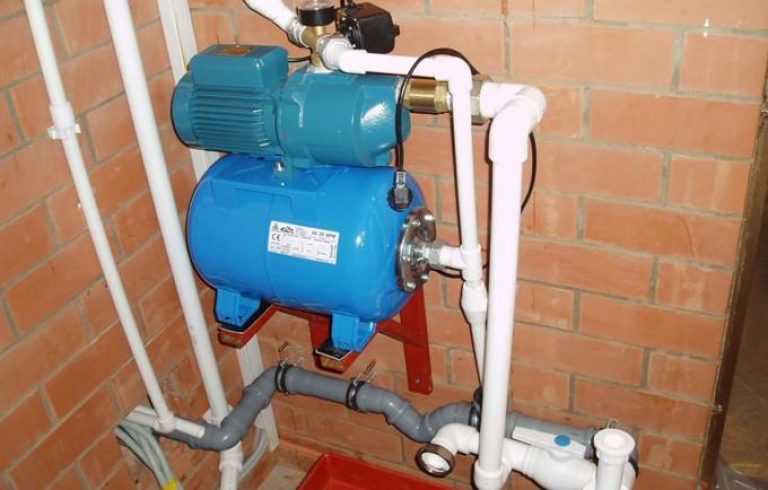
Calculation of almost any accumulators for domestic water supply stations will show that it is necessary to use a tank with a volume of 25-50 liters. This is the optimal volume for most pumps for wells and wells, which will be enough for a full water supply of a private house. You do not need to call specialists to connect a hydraulic tank and put it into operation, you can do it yourself. The tank is mounted on the floor or wall with the help of anchors, and it is absolutely necessary to lay a gasket of vibration-proof material under the mounting plate. Pipes are connected to the branch pipe of the storage tank through special flexible adapters that come with it.
After the installation of the tank is completed, it is adjusted - initially you need to determine the pressure in the accumulator, which can be done using a conventional pressure gauge. On the tank body you will find a spool to which the measuring device is connected. The normal pressure level is 1.5 Bar, if its actual value differs, then it is necessary to pump air using a pump.
As already mentioned, the water inside the tank is in a rubber "pear" surrounded by air. The more air in the tank, the more the pear shrinks and loses its maximum size. And vice versa - the less air, the larger and more capacious the pear, but the lower the pressure of the water supply. You can adjust the pressure within 1-2 Bar at your discretion, achieving the desired operating mode of the hydraulic tank.
It is also necessary to adjust the pressure switch. Under the cover of the relay housing is a pair of springs (large and small). Changing their position allows you to set the minimum and maximum pressure level at which the station will turn on the pump. For the minimum level at which the water supply begins, a large spring is responsible. The small spring sets the required pressure difference.
The most common failure of the accumulator is the loss of tightness between the working media - water and air, which occurs due to wear or damage to the rubber membrane (pear).
The reason for the depressurization of the membrane is the wear of rubber, which occurs due to its stretching with water at an insufficient level of air pressure in the tank. Also, accelerated wear provokes accelerated pumping of water from the tank - after complete emptying, the membrane is folded into a flat sheet with strongly curved edges.

Trying to restore the worn membrane with your own hands is pointless, since no latches will return it to complete tightness. You will need to buy a new membrane that matches the size of your tank and replace the damaged part.
The algorithm of actions is as follows:
- A complete discharge of water from the tank is performed and the tank is disconnected from the pipeline.
- The bolts securing the flange on the back of the tank are unscrewed, the nut of the air pump spool is also dismantled.
- The spool is pushed through the hole into the tank, after which the membrane is removed from the housing.
- The internal cavity of the tank, if necessary, is cleaned of corrosion and deposits using sandpaper or a brush for metal.
- The installation of a new membrane is carried out, the spool is threaded and fixed with a nut.
- The edges of the membrane are leveled at the neck of the container, after which a flange is mounted with a uniform tightening of the bolts.
- After assembly, the calculated amount of air is pumped into the accumulator and 12 hours are expected, after which the tank is checked for leaks. If there is no pressure loss, the device is connected to the supply pipe.

Also, there are often problems with bleeding air from the tank, which is caused by the deformation of the spool. The loss of air is quite simple to eliminate, you just need to buy a metal cap with a rubber gasket in the car shop and screw it onto the spool.
The accumulator is a special metal sealed container containing inside an elastic membrane and a certain amount of water under a certain pressure.
A hydraulic accumulator (in other words, a membrane tank, a hydraulic tank) is used to maintain stable pressure in the water supply system, protects the water pump from premature wear due to frequent switching on, and protects the water supply system from possible water hammer. When you turn off the voltage, thanks to the accumulator, you will always be with a small supply of water.

Here are the main functions that the accumulator performs in the water supply system:
- Protecting the pump from premature wear. Due to the supply of water in the membrane tank, when the tap is opened, the pump will only be switched on if the supply of water in the tank runs out. Any pump has a certain rate of inclusions per hour, therefore, due to the accumulator, the pump will have a stock of unused inclusions, which will increase its life.
- Maintaining constant pressure in the water supply system, protection against drops in water pressure. Due to pressure differences, when several taps are turned on simultaneously, sharp fluctuations in water temperature occur, for example, in the shower and in the kitchen. The accumulator successfully copes with such unpleasant situations.
- Protection against water hammer, which can occur when the pump is turned on, and can spoil the pipeline in order.
- Maintaining a supply of water in the system, which allows you to use water even during a power outage, which in our time happens quite often. This feature is especially valuable in country houses.
Accumulator device
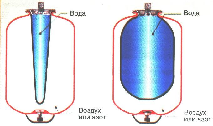
The sealed housing of this device is divided by a special membrane into two chambers, one of which is designed for water, and the other for air.
Water does not come into contact with the metal surfaces of the body, as it is located in a water chamber-membrane made of strong butyl rubber material that is resistant to bacteria and meets all hygiene and sanitary standards for drinking water.
In the air chamber is a pneumatic valve, the purpose of which is to regulate the pressure. Water enters the accumulator through a special connecting pipe on the thread.
The accumulator device must be mounted in such a way that it can be easily disassembled in case of repair or maintenance, without draining all the water from the system.
The diameters of the connecting pipe and the discharge pipe should match, if possible, then this will avoid undesirable hydraulic losses in the system pipeline.
In the membranes of hydraulic accumulators with a volume of more than 100 l there is a special valve for bleeding air released from the water. For small-sized accumulators in which there is no such valve, a device for bleeding air, for example, a tee or a tap, which closes the main line of the water supply system, must be provided in the water supply system.
In the accumulator air valve, the pressure should be 1.5-2 atm.
The principle of operation of the accumulator
The accumulator works like this. The pump delivers pressurized water to the pressure accumulator membrane. When the pressure threshold is reached, the relay switches off the pump and water stops flowing. After the pressure starts to drop during the intake of water, the pump switches on again automatically and supplies water to the accumulator membrane. The larger the volume of the tank, the more effective the result of its work. The operation of the pressure switch can be adjusted.
During operation of the accumulator, air dissolved in water gradually accumulates in the membrane, which leads to a decrease in the efficiency of the device. Therefore, it is necessary to prevent accumulator, bleeding the accumulated air. The frequency of preventive measures depends on the volume of the tank and the frequency of its operation, which is approximately once every 1-3 months.

These devices can be of vertical and horizontal configuration.
The principle of operation of the devices has no differences, except that the vertical accumulators with a volume of more than 50 l in the upper part have a special valve for bleeding air, which gradually accumulates in the water supply system during operation. Air accumulates in the upper part of the device, because the location of the valve for bleeding is selected in the upper part.
In horizontal devices for bleeding air, a special tap or drain is installed, which is installed behind the accumulator.
Of devices of small sizes, regardless of whether they are vertical or horizontal, air is vented by completely draining the water.
Choosing the shape of the tank, proceed from the size of the technical room where they will be installed. It all depends on the dimensions of the device: which one fits better in the space allotted for it, this will be installed, regardless of whether it is horizontal or vertical.
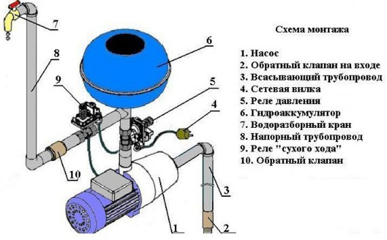
The accumulator connection diagram
Depending on the assigned functions, the connection diagram of the accumulator to the water supply system may be different. The most popular accumulator connection diagrams are given below.

Such pumping stations are installed where there is a large water consumption. As a rule, one of the pumps at such stations operates continuously.
On the up pumping station the hydraulic accumulator serves to reduce pressure surges during switching on of additional pumps and to compensate for small water intakes.
Another such scheme is widely used when a frequent interruption in the supply of electricity to booster pumps occurs in the water supply system, and the presence of water is vital. Then the water supply in the accumulator saves the situation, playing the role of a backup source for this period.
The larger and more powerful the pumping station, and the greater the pressure it must maintain, the greater the volume of the hydraulic accumulator, which acts as a damper, should be.
The buffer capacity of the hydraulic tank also depends on the volume of the required water supply, and on the difference in pressure when the pump is turned on and off.

For long and uninterrupted operation submersible pump must make from 5 to 20 inclusions per hour, which is indicated in its technical characteristics.
When the pressure in the water supply system drops to the minimum value, the pressure switch automatically turns on, and at the maximum value, it turns off. Even the smallest water flow rate, especially in small water supply systems, can reduce the pressure to a minimum, which will instantly give a command to turn on the pump, because the water leak is compensated by the pump instantly, and after a few seconds, when replenishing the water supply, the relay will turn off the pump. Thus, with minimal water consumption, the pump will work almost idle. This mode of operation adversely affects the operation of the pump and can quickly disable it. The position can be corrected by a hydraulic accumulator, which always has the required supply of water and successfully compensates for its insignificant consumption, and also protects the pump from frequent switching on.
In addition, the accumulator, connected to the circuit, smooths out a sharp increase in pressure in the system when the submersible pump is turned on.
The volume of the tank is selected depending on the frequency of switching on and the power of the pump, the flow rate of water per hour and the height of its installation.

For the storage water heater in the wiring diagram, the accumulator plays a role expansion tank. When heated, the water expands, increasing the volume in the water supply system, and since it does not have the ability to compress, the smallest increase in volume in a confined space increases pressure and can lead to the destruction of water heater elements. Here, too, a hydraulic tank will come to the rescue. Its volume will directly depend on and increase from an increase in the volume of water in the water heater, an increase in the temperature of the heated water and an increase in the maximum allowable pressure in the water supply system.

The hydraulic accumulator is connected before the booster pump along the water. It is needed to protect against a sharp decrease in pressure in the water supply network when the pump is turned on.
The capacity of the accumulator for the pumping station will be the greater, the more water is used in the water supply system and the smaller the difference between the upper and lower pressure scales in the water supply in front of the pump.
How to install a hydraulic accumulator?
From the foregoing, it can be understood that the device of the accumulator is absolutely not like an ordinary water tank. This device is constantly in operation, the membrane is constantly in dynamics. Therefore, the installation of the accumulator is not so simple. The tank must be strengthened during installation reliably, with a margin of safety, noise and vibration. Therefore, the tank is fixed to the floor through rubber gaskets, and to the pipeline through rubber flexible adapters. You need to know that at the inlet of the hydraulic system, the supply section should not be narrowed. And one more important detail: for the first time, the tank must be filled very carefully and slowly, using a weak pressure of water, in case the rubber bulb has stuck from a long period of inactivity, and with a sharp pressure of water it can be damaged. It is best to remove all air from the pear before putting it into operation.
The accumulator must be mounted so that during operation it can be freely approached. It is better to entrust this task to experienced specialists, since very often the tank breaks down due to some unaccounted for, but important trifle, for example, due to a mismatch in the diameter of the pipes, unregulated pressure, etc. It is impossible to conduct experiments here, because the normal operation of the water supply system is at stake.

So you brought a purchased tank to the house. What to do next with it? It is immediately necessary to find out the pressure level inside the tank. Typically, the manufacturer pumps it up to 1.5 atm, but there are times when, due to a leak, indicators are reduced by the time of sale. To make sure that the indicator is correct, you need to unscrew the decorative cap on an ordinary automobile spool and check the pressure.

How to check it? Usually a manometer is used for this. It can be electronic, mechanical automobile (with a metal case) and plastic, which comes with some models of pumps. It is important that the pressure gauge has greater accuracy, since even 0.5 atm changes the quality of the hydraulic tank, so it is better not to use plastic pressure gauges, since they give a very large error in performance. These are usually Chinese models in a weak plastic case. The indicators of electronic pressure gauges are affected by the battery charge and temperature, in addition, they are very expensive. Therefore, the best option is an ordinary automobile pressure gauge that has passed the test. The scale should be on a small number of divisions, in order to be able to more accurately measure pressure. If the scale is designed for 20 atm, and you need to measure only 1-2 atm, then you can not expect high accuracy.

If there is less air in the tank, then there is a larger supply of water, but the pressure difference between an empty and an almost full tank will be very significant. It's all about preferences. If it is necessary that the water supply constantly has a high water pressure, then the tank should have a pressure of at least 1.5 atm. And for domestic needs, 1 atm may well be enough.
At a pressure of 1.5 atm, the hydraulic tank has a smaller supply of water, because of which the booster pump will turn on more often, and in the absence of light, the supply of water in the tank may simply not be enough. In the second case, you will have to sacrifice pressure, because you can take a shower with a massage when the tank is full, and as it is empty, only the bath.
When you decide what is more important for you, you can set the desired mode of operation, that is, either pump air into the tank or bleed excess.
It is undesirable to lower the pressure below 1 atm, as well as excessively exceed it. A pear filled with water at insufficient pressure will touch the walls of the tank, and can quickly become unusable. And excessive pressure will not allow to pump a sufficient amount of water, since most of the tank will be occupied by air.
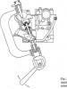
Pressure switch setting
You also need to configure the pressure switch. Opening the cover, you will see two nuts and two springs: large (P) and small (delta P). With their help, you can adjust the maximum and minimum pressure levels at which the pump turns on and off. A large spring is responsible for turning on the pump and pressure. By design, you can see that it, as it were, promotes water to close the contacts.
![]()
Using a small spring, the pressure difference is set, as stipulated in all instructions. But the instructions do not indicate a reference point. It turns out that the reference point is the spring nut P, \u200b\u200bthat is, the lower limit. The lower spring, which is responsible for the pressure difference, resisting the pressure of water, pushes the movable plate from the contacts.

When the correct air pressure has already been set, the accumulator can be connected to the system. By connecting it, you need to carefully monitor the manometer. All accumulators show the normal and maximum pressure values, the excess of which is unacceptable. Manual disconnection of the pump from the network occurs when the normal accumulator pressure is reached, when the limit value of the pump head is reached. This happens when the pressure increase stops.
The pump capacity is usually not enough to pump the tank to the limit, but this is not even particularly necessary, because pumping reduces the life of the pump and pear. Most often, the pressure limit for disconnection is set at 1-2 atm higher than inclusion.
For example, when the pressure gauge is 3 atm, which is enough for the needs of the owner of the pumping station, you need to turn off the pump and slowly turn the small spring nut (delta P) to decrease, until the mechanism triggers. After that, you need to open the tap and drain the water from the system. Observing the pressure gauge, it is necessary to note the value at which the relay turns on - this is the lower pressure limit when the pump turns on. This indicator should be slightly higher than the pressure indicator in an empty accumulator (by 0.1-0.3 atm). This will make it possible to serve a pear for a longer period of time.
When the nut of the large spring P is rotated, a lower limit is set. To do this, turn on the pump in the network and wait until the pressure reaches the desired level. After that, it is necessary to adjust the nut of the small spring "Delta P" and finish the adjustment of the accumulator.

In the air chamber of the accumulator, the pressure should be 10% lower than the pressure when the pump is turned on.
An exact indicator of air pressure can be measured only when the tank is disconnected from the water supply system, in the absence of water pressure. Air pressure must be constantly monitored, adjusted as necessary, which will add to the membrane lifespan. Also, in order to continue the normal functioning of the membrane, a large pressure drop must not be allowed when the pump turns on and off. A difference of 1.0-1.5 atm is normal. Stronger pressure drops reduce the life of the membrane, stretching it greatly, in addition, such pressure drops do not allow comfortable use of water.
Hydraulic accumulators can be installed in places with low humidity, not subject to flooding, so that the flange of the device can serve successfully for many years.
When choosing the brand of the hydraulic accumulator, it is necessary to pay special attention to the quality of the material the membrane is made of, check certificates and sanitary certificates, making sure that the hydraulic tank is designed for systems with drinking water. You also need to make sure there are spare flanges and membranes that should be included, so that in case of a problem you do not have to buy a new hydraulic tank.
The maximum pressure of the accumulator for which it is designed must not be less than the maximum pressure in the water supply system. Therefore, most devices withstand a pressure of 10 atm.

To determine how much water can be used from the accumulator when the power is turned off, when the pump stops pumping water from the water supply system, you can use the fill table of the membrane tank. The water supply will depend on the setting of the pressure switch. The higher the pressure difference when turning the pump on and off, the greater the supply of water will be in the accumulator. But this difference is limited for the reasons stated above. Consider the table.

Here we see that in the membrane tank with a volume of 200 l when the pressure switch is set, when the pump on indicator is 1.5 bar, the pump off is 3.0 bar, the air pressure is 1.3 bar, the water supply will be only 69 l, which is approximately one third of the total tank volume .
Calculation of the required volume of the accumulator
To perform the calculation of the accumulator, use the following formula:
Vt \u003d K * A max * ((Pmax + 1) * (Pmin + 1)) / (Pmax - Pmin) * (P + 1),
- Amax - maximum consumption of liters of water per minute;
- K is a coefficient that depends on the power of the pump motor;
- Pmax - pressure when the pump is turned off, bar;
- Pmin - pressure when turning on the pump, bar;
- Rd. - air pressure in the accumulator, bar.
As an example, we select the necessary minimum accumulator volume for the water supply system, taking, for example, the Aquarius BTsPE 0.5-40 U pump with the following parameters:
| Pmax (bar) | Pmin (bar) | Bar (bar) | A max (cubic m / hour) | K (coefficient) |
| 3.0 | 1.8 | 1.6 | 2.1 | 0.25 |
Using the formula, we calculate the minimum volume of HA, which is 31.41 liters.
Therefore, we choose the next closest GA size, which is 35 liters.
The tank volume in the range of 25-50 liters is ideally consistent with all the methods for calculating the volume of HAs for domestic water systems, as well as with the empirical designations of different manufacturers of pumping equipment.
With frequent power outages, it is advisable to choose a larger tank, but at the same time it should be remembered that water can fill the tank only 1/3 of the total volume. The more powerful the pump is installed in the system, the greater should be the volume of the accumulator. This conformity of dimensions will reduce the number of short starts of the pump and extend the life of its electric motor.
If you bought a large accumulator, you need to know that if you do not use water regularly, it stagnates in the tank and its quality deteriorates. Therefore, choosing a hydraulic tank in the store, you need to consider the maximum amount of water used in the house's water supply system. Indeed, with a small flow of water, it is much more expedient to use a tank with a volume of 25-50 liters than 100-200 liters, in which water will be wasted in vain.
Accumulator repair and prevention
Even the simplest hydraulic tanks require attention and care, like any working and beneficial device.
Reasons for repairing the accumulator are different. This is corrosion, dents in the housing, a violation of the integrity of the membrane or a violation of the tightness of the tank. There are also many other reasons that oblige the owner to repair the hydraulic tank. In order to prevent serious damage, it is necessary to regularly inspect the surface of the accumulator, monitor its work to prevent possible problems. It is not enough to inspect the GA twice a year, as stipulated in the instructions. After all, one malfunction can be eliminated today, and tomorrow you can not pay attention to another problem that has arisen, which within six months will turn into an irreparable and can lead to failure of the hydraulic tank. Therefore, the accumulator must be inspected at every opportunity so as not to miss the slightest malfunctions, and to repair them in time.
Causes of breakdowns and their elimination
![]()
The cause of the breakdown of the expansion tank may be too frequent on-off of the pump, water outlet through the valve, weak water pressure, weak air pressure (lower than calculated), weak water pressure after the pump.
How to fix the malfunction of the accumulator with your own hands? The reason for the repair of the accumulator can be weak air pressure or its absence in the membrane tank, damage to the membrane, damage to the housing, a big difference in pressure when the pump is turned on and off, the wrong tank volume.
You can troubleshoot as follows:
- to increase the air pressure, it is necessary to pump it through the tank nipple with a garage pump or compressor;
- a damaged membrane can be repaired at a service center;
- a damaged case and its tightness is also eliminated in the service center;
- it is possible to correct the difference in pressure by setting the differential too large in accordance with the frequency of switching on the pump;
- the adequacy of the tank volume must be determined before it is installed in the system.
Accumulator The principle of operation, purpose and configuration.
Expansion tank, expansion tank, accumulator - this is the same !!!

In this article you will learn:
Definition and purpose.
Accumulator - This is a special element that serves to take on the volume of fluid, thereby taking away excess pressure. And return the fluid to maintain pressure. The goals are actually three, but they intersect with each other.
The first goal is the ability to accumulate (accumulate) a volume of liquid.
The second goal is to collect excess pressure by accumulating fluid.
The third goal - few people know about it - is the quenching of water hammer in the system and heating. That is why even the smallest accumulators in volume have such a large thread of one inch (1 ").
Most people who come and read this article will come across those visitors who have problems with their accumulators. And so, first of all, we will satisfy their interest.
To understand the next fault, you need to see the circuit automatically.

This scheme is discussed in this article: Training course. Do-it-yourself automatic water supply.
How to determine the malfunction of hydraulic accumulators in an automatic water supply system of a private house:
1. Water began to go in small portions. That is, repeated periodic spitting of water from the tap in small portions occurs.
2. The pressure gauge needle jumps sharply up and drops to zero.
If these symptoms are present, First of all, check the following: While observing the pressure gauge, press the spool valve, releasing air. If the needle on the manometer sharply went down, then there is very little air. Hold the spool and bleed all the air to the end. If water goes, the membrane is torn. If not, then the membrane is whole and air escapes through slots or a spool. What to do next will be described below.
How to determine the malfunction of accumulators in hot water:
Parameters of accumulators.
Each accumulator is equipped with two main parameters:
1. Operating maximum pressure. On average, for water supply 6-8 atmospheres (bar). For heating 5 Bar.
2. The volume of the accumulator. The accumulator itself, which we see from the outside, is this external form in volume and is indicated in the passport or on the label. The liquid that the accumulator can take is much lower, maybe even half, it depends on the pressure amplitude (the difference between the upper and lower pressure limits). The higher the difference, the more the battery can accept.
Each accumulator must be checked for a permissible pressure value of the charged air. The accumulator has a pipka spool like a car wheel. To check and set the required air pressure, you will need a regular car pump, which inflate the car wheels. Preferably with a pressure gauge that shows the pressure inside the tire. Pressure gauges for automobile pumps have a Pascal scale (Pa, MPa). That is, on a manometer, a scale of 0.1 MPa will be equal to one atmosphere (1 Bar).
We will talk about how much air should be pumped below.
Hydraulic accumulator in the water supply system.
Setting up the accumulator for hot water supply.
Information on how to connect in the apartment.
On hot, you can use the blue accumulators. In addition, their working pressure threshold is higher than that of red accumulators.
First, consider the schemes where the accumulator is installed.
Scheme 1.

Scheme 2.

Scheme 1 helps to save more materials for connecting the accumulator, it also helps to make assembly easier and more efficient. The difference between circuit 1 and circuit 2 is not significant. It is better to choose scheme 2, since more cooled water will enter the accumulator.
As for the volume, then the volume for hot water is 5-10% of the volume of heated water. That is, if the volume of heated water is 300 liters, then the volume of the accumulator according to the passport will be 15-30 liters. A matter of taste, the more the better. If these are large volumes of heated water of 300-500 liters, then 5% is suitable. If small up to 100 liters, then 10% of the volume of heated water. For central water supply, it is better to use larger volumes of accumulators. Since the pressure there is very unstable and getting under the right pressure is very difficult. There is a large spread of pressure.
Pressure accumulator for hot. This is also a difficult question, so far there are two areas in which you can navigate:
1. The average value between the minimum water supply pressure and the pressure relief valve. This is actually conditionally valid. More is less, and the accumulator will still work, perhaps even for a long time. Usually at 6 bar. The minimum pressure in the central water supply is about 2 bar. And that average is 4 bar.
2. Accurate pressure calculation. An accurate calculation helps to understand factors such as: the life of the membrane, obtaining the maximum efficiency of the accumulator.
To get a calculation, you need to identify the task or factors that influence these calculations.
The first factor: - is to obtain maximum efficiency (coefficient of performance).
The second factor: Obtaining a long service life of the accumulator.
Obtaining maximum efficiency is expressed by obtaining maximum accumulation of water in the accumulator. That is, to obtain such parameters that are able to accept as much water as possible during expansion.
The most basic problem of failure or functioning of the accumulator is the depressurization of two different media (water and air). When the rubber membrane breaks, depressurization occurs. Also, there are cases when air escapes from the accumulator, thereby reducing the pressure in the accumulator, which leads to incorrect parameters of the accumulator. Often the spool starts to release air, and in order to exclude the influence of the spool, it is necessary to tighten a metal cap with a rubber gasket, which is sold in car dealerships. This kalapachek excludes an air exit through a faulty spool. You can also try to tighten the pipka nut. See image.

What causes the rubber membrane to break? The membrane breaks due to the banal wear of rubber by constant expansion, contraction and bending of the rubber. But there is one reason that greatly increases the wear of the rubber membrane, but more on that later ...
There is an opinion that when there is not enough air in the accumulator, the membrane expands greatly, thereby greatly stretching the rubber, ultimately leading to rupture of the membrane. Seeing which membranes are in the hydraulic accumulator, one is led to the idea that this cannot be, since the membranes themselves are large enough to expand to fill or repeat the entire external volume of the hydraulic accumulator without causing strong stretch marks. That is, they especially do not stretch there to break themselves by stretching.
The main reason for the rapid wear of rubber, at least, it seems to me that way, you can think differently, but I put it this way: This is when there is a quick return of water by a hydraulic accumulator. That is, water quickly leaves the accumulator as a result of a decrease or absence of pressure c. When you open the valve to the full extent, the pressure in the system decreases and the accumulator starts to discharge water, and as soon as the water in the membrane has ended, the membrane sharply folds into a flat sheet. The edges of the so-called sheet are strongly bent. And the greater the pressure difference between air and water, the more destructive it is for a rubber membrane. In other words, it turns back water hammer. Constant such sharp or even slow folding of the membrane is very detrimental to rubber.
Of course, I do not argue with you, you can trust specialists who think differently. But how would you put it. Very, many people and specialists are still pumping a lot of pressure into the accumulator, motivating this not to greatly expand the membrane. Or even believing that the membrane should not expand at all, only in rare cases. That is, some experts, pumping heavily a hydraulic accumulator, suggest that the extensions, as it were, should not exist at all, and if the extensions suddenly appear, they will be very rare phenomena. Thus, as if mistakenly believing that the rubber will be in constant rest for a long time (in the form of a folded sheet), thereby increasing the service life. Are they wrong?
The water in the accumulator constantly expands when heated, and the accumulator will constantly alarm.
Therefore, it is not advisable to have a membrane in the accumulator, which becomes a rolled sheet. This is detrimental to the membrane.
And so, the above proof - it gives one identity is that the membrane should not, from time to time, fold into a sheet. And so that the membrane does not collapse into the sheet, it is necessary that the air pressure in the accumulator be less than the water pressure. As if the membrane in the accumulator should be constantly filled.
And in order to get the maximum efficiency of the accumulator, it is necessary that in the quiet mode the water in the accumulator be as small as possible.
The exact calculation will be for the apartment: Pump the accumulator with air to a pressure lower than the minimum water pressure. That is, it is necessary either from experience or from figures from specialists to find out what pressure is in your house, but it is better to find out what minimum pressure is in your apartment. But consider one more fact! When you open the faucet in the kitchen or in the bathroom, the pressure drops - this is a fact! Therefore, subtract another atmosphere from the minimum pressure and get the pressure that must be given to the air in the accumulator. The pressure will be less than the minimum water pressure by 1 Bar.
You can also check central water pressure on your own! There are some ways to check:
1. Pump the accumulator with air to one atmosphere. Connect it to water. And after a moment, the air pressure in the accumulator will be equal to the pressure of the water. And connect the pump to the accumulator and it will show you the pressure. After you know the pressure, it is necessary to turn off the water supply taps and lower the pressure of the hot water supply to zero. And start pumping the right pressure.
2. The second method is only suitable if there is a tap between the accumulator and the system. Pump up the accumulator to 4 atmospheres, connect it to water. Turn on the tap - if water began to flow into the accumulator (Listen and you will hear), then the water pressure is above 4 atmospheres. If not, close the tap. Blow air from the accumulator to 3 atmospheres. Open the tap - and if the water rumbles (the sound of flowing water in the pipe). Water should flow for at least 3-5 seconds. You just do not confuse this murmur filling filling leading to the accumulator. The second method requires a lot of experience or technical engineering thinking. It makes it possible to immediately set the pressure of the accumulator by releasing air from the accumulator, without resorting to additional pumping.
Accurate calculation for a private house: Pump the accumulator with air to a pressure lower than the minimum water pressure, by 1bar. That is, if your minimum pressure on the pressure gauge is 1.5 Bar, then the air pressure in the accumulator should be 0.5 Bar.
Setting up the accumulator for water heating.
Firstly, when pumping air into the accumulator, you need to disconnect it from. It is necessary that there is no water in it.
Here we will not consider the scheme, since any water heating system has an expansion tank or a hydraulic accumulator. The accumulator is connected to the central main return pipe. Closer to the boiler or. But this does not mean that if you install it in another place, it will not work.
The main task of the accumulator in a water heating system - it is to extinguish pressure surges when the temperature of the heat carrier changes. In this problem, a large cross-flow to the coolant accumulator is not required. It is enough to even connect the accumulator with a regular flexible hose, which we connect the toilet tank to. But in some cases, it is necessary to increase the diameter of the inlet pipe to the accumulator: In cases of dirty rusty water, in order to exclude clogging and accumulation of sand in the pipe (20 mm). And in cases where it is necessary to further protect
The accumulator is a tank that operates under a certain pressure. This device accumulates hydraulic energy, and, if necessary, returns it back to the system, of which it, in fact, is a part. For the correct functioning of the device, precise adjustment of the accumulator is necessary.
In fact, the specified device performs the same work as the water tower, but the latter does not have external pressure that would be exerted on the liquid, so the accumulator and the tower are fundamentally different things.
Water batteries accumulate energy in various ways, which leads to their separation into different types. And they are as follows:
- A device with a mechanical drive.
- A device equipped with a pneumatic storage.
Batteries that carry out their work using a mechanical storage device, are endowed with a large number of disadvantages, which is why they are rarely used. However, pneumatic accumulators also have not only positive characteristics. Consider the advantages along with the disadvantages of this kind of products.
Benefits
The properties that accumulators possess depend on the type of device.
Cargo:
- The device maintains a constant pressure.
- The device has a fairly large working volume.
- Differs in the low price.
Spring loaded:
- It has a relatively high energy intensity.
- It has a low cost.
Pneumohydraulic:
- It is endowed with a sufficiently high level of energy intensity, while having minimal dimensions.
- It can be made in various variations (meaning the design of the device).
- It has minimal inertia.
- Maximum reliability with a relatively simple design.
disadvantages
Cargo:
- It has a low energy intensity.
- There is a fairly high inertia.
- It has a large size.
- The pressure in the apparatus is quite low.
- The reliability of the device is very small and there is a possibility of leakage of the piston seal.
Spring loaded:
- The pressure directly depends on which spring is installed in this unit. This indicator is also affected by the amount of filling.
- The working volume is relatively small.
- There is some inertia.
- Very low reliability. There is a high probability of leakage of the seal, as well as malfunction of the spring.
Pneumohydraulic:
The pressure in the apparatus varies non-linearly with respect to the filling volume and depends on its speed.
Customization
Hydraulic accumulators are used both in everyday life and in industry. The most popular among these devices is a pneumohydraulic accumulator, which is a container with a special elastic membrane located inside the device. The specified element is designed to maintain optimal water pressure, which is located in the water supply system of the house.
Most often, hydraulic accumulators are operated as components of autonomous water supply systems in summer cottages and in country houses.
In the mentioned cases of using this device, it is necessary to remember that the city water supply has a pressure of one and a half atmospheres. So, the accumulator must be adjusted to this indicator in order to ensure normal operation.
Of course, one atmosphere to fill the rubber tank will also be enough. But this will provoke a change in the mode of functioning, which is associated with different pressures. In order to avoid such consequences, the accumulator installed in the country should be adjusted.
Before setting up the device, check the air pressure. To achieve this, a commonplace automobile pressure gauge is suitable. The only requirement is that it must have a minimum graduated scale value. To accomplish this task, you just need to connect the pressure gauge to the hydraulic accumulator spool.
Further, taking into account the preferred mode of operation of the device, either pumping or air bleeding from the tank is performed. During this operation, it is important to carefully monitor the pressure level - it must remain between 1 and 1.5 atmospheres in order to exclude the possibility of damage.
The pressure switch can be adjusted so that it turns the pump on and off at strictly defined values \u200b\u200bof the specified value. The adjustment is related to the impact on the spring regulators. One of them, the one that is large, fixes the lower pressure limit, which determines the activation of the pump. The second, which is smaller, captures the difference between the upper and lower boundaries of this quantity.
When all changes are completed, the accumulator is connected directly to the functioning system, after which it is launched.
The adjustment is completed with the following manipulations:
- During pump operation, it is necessary to determine the pressure value that will be most acceptable in a particular case.
- Switch off the pump and, using the small regulator, reduce the difference in pressure limits until the relay trips.
- Open the tap and drain the water in the system, observing, at the same time, the gauge scale. As soon as the pump starts, it is necessary to immediately take readings from the pressure gauge. This value is the lower limit of the pressure level.
- Using the large knob, set the lower limit.
- Connect the pump to the mains and wait until the pressure rises to the desired level.
- After that, adjust the small knob.
Along with this, there is a possibility that you will have to disconnect the pump from the mains in manual mode. Such a situation is possible when the device reaches operating pressure and if a pressure is formed in the pump that exceeds the maximum permissible norms.
It should be borne in mind that it is necessary to carefully compare the data obtained when using the manometer and the indicators published in the technical passport of the accumulator itself. Exceeding the values \u200b\u200bof the working, as well as the maximum pressure is strictly unacceptable.