Possible malfunctions of the fecal pump. Main pump malfunctions
The use of a drainage fecal unit in a private area is a universal phenomenon, since most often an individual sewage system and water supply system is equipped at such facilities. High-quality pumping equipment can drive the entire system, preventing the flooding of privately owned objects or the failure of one of the collectors. However, do not forget that a good fecal aggregate (regardless of the manufacturer and its capacity) requires periodic maintenance. Otherwise, there is a risk of "losing" the unit for a while or forever.
For what reason is the breakdown of the fecal pump and how to deal with it, we tell below.
Important: the causes of the malfunction of the fecal pump and the need for subsequent repair are the following points:
- Incorrect operating conditions (i.e. excess load on the device or incomplete immersion);
- Untimely preventive maintenance of the pump;
- Incorrectly mounted pump;
- Production defect.
What does a working pump look like?
When conducting technical inspection and maintenance, in order to avoid further repairs, you should always pay attention to such points:
- Air blown into the pump nozzle must pass freely through the entire working cavity and exit the hole. If this did not happen, then most likely there is an air plug. It will have to be eliminated through a simple repair.
- The piston of the unit must be intact, without visible damage and monolithically elastic.
- The distance between the electromagnetic coils and the piston should also be monitored. Ideally, it should be in the range of 0.4-0.5 cm. Here everything should be exactly as in a pharmacy. Since if the distance is smaller, there is a risk of overheating and combustion of the engine. If the distance is large, then the magnetic coils will simply beat and fail.
- Important when servicing the pump is also the distance between the pump valves and the inlets. It should be about 0.7-0.8 mm.
The simplest causes of pump failure

- Repair of the fecal aggregate can be avoided by checking the input voltage at the stage of its failure. It is it (or rather its differences) that is often the reason why the fecal pump stops working. Therefore, before proceeding with the repair and disassembly of the pump, check the mains voltage. If the voltage is all right, then you will have to further identify the causes of the breakdown and repair the equipment.
- Another reason that the fecal pump refuses to work is the air plug. This problem occurs due to incomplete immersion of the pump in the active medium or its improper installation (tilt to either side). In this case, rinse the unit and lower it again into the pumped liquid. To eliminate airing, the pump should be tilted slightly so that the liquid completely displaces air from its working chamber.
- It also happens that the float in the submersible fecal pump simply does not work. It is enough to remove the unit, rinse it and lower it into a bucket of water. If the pump does not work, raise the float and monitor its actions. The unit wound up - it means the matter is a float that is clogged or simply stuck with fecal masses. It must be carefully inspected and raised several times to lower.
Important: in the middle of the float is a metal ball, which, depending on the water level in the pit, closes or opens the electric circuit.
At the same time, it is worth remembering that the reason why the fecal pump does not pump water may be too much power of the unit. In this case, the pump works hard, and the water just does not have time to seep to the impellers of the equipment. To remedy the situation, just try lowering the implement to a greater depth.
Mechanical damage to the pump

The reasons for the failure of the fecal pump can be mechanical damage. So, if any part of the mechanism of the unit has broken off, it may well jam the working blades of the pump. To check and confirm / refute this item when repairing the pump, it is necessary to turn the blades by hand. If they spin easily, then the reason is not a breakdown. If the blade rotates with difficulty, then there will be a more complicated repair of the unit and its disassembly.
Important: a hard-rotating impeller may be the result of a failure of the bearing system.
Electrical problems
If the submersible fecal pump does not have protection against dry running, then the windings of the mechanism can be burned here. An obvious sign may be the buzz of the switched on unit and strong heating / melting of the cable. In this case, when carrying out repairs, it will be necessary to replace the winding, which, by the way, can be seen well and without disassembling the device.
Important: to avoid complicated repair of the fecal aggregate, it is worth periodically flushing the pump in clean water and pumping it. This will avoid sticking parts of the mechanism with particles of feces. In addition, try to avoid exceeding the allowable fraction size that the pump can pump.
Centrifugal pumps are designed for pumping liquids. Constructions centrifugal pumps very diverse, characterized by the reliability necessary for industrial and individual tasks, high efficiency, low ripple. But like any mechanism, a centrifugal pump must be operated under certain conditions. Otherwise, the probability of failures increases.
Centrifugal Pump Operating Conditions
If at work pumping equipment failures were noticed, their reason may be in the working conditions, and not in the hardware. Before disassembling and repairing the pump, it is necessary to find out whether the rules for its operation were observed. If extraneous noise is heard during pump operation or the pump’s working chamber is not completely filled with water, it may be necessary to bleed the air accumulated inside the product. To do this, open the exhaust air valves located on the pump housing. After that, fill the suction pipe and the pump itself with water (working fluid) until the air exits the system completely.
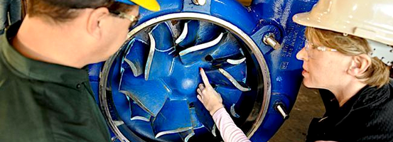
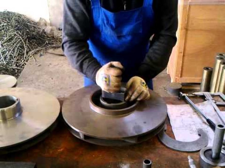
impeller of an industrial centrifugal pump
Check if the suction pipe, impeller blades and filter screen are clogged. If these parts become contaminated, the pump performance may drop, the pressure will decrease, the fluid will be pulsed. To eliminate the likelihood of such blockages, it is necessary to install before the pump mechanical filter rough cleaning. In some cases, to quickly solve the situation in order to increase the pressure of the centrifugal pump, you can increase the speed of rotation of the impeller.
With an increase in the fluid supply rate, the pump power increases, which can lead to engine overload. To eliminate this situation, a valve is installed on the outlet pipe, which restricts the flow of water. This solution not only normalizes the load on the engine, but will prevent its overheating.
It is important that the direction of rotation of the pump shaft matches the desired one. Otherwise, the fastening nuts may loosen and the shaft will run out, which is likely to cause damage to parts and the pump casing.
Avoid exceeding the height of the liquid suction level. This can lead to a water hammer during a spasmodic flow of fluid, reduces pump power, and has a negative effect on other connected equipment.
For reliable and stable operation of the centrifugal pump, it is necessary to monitor the following parameters:
- fluid temperature
- water supply diameter
- water supply length
- number of pipe turns, angle of rotation
In general, to reduce losses during fluid movement in the pipeline and, accordingly, to reduce the load on the pump, it is necessary to use a short pipe of increased diameter. An increased diameter will be especially in demand if it is not possible to reduce the length of the pipeline. Also, excessive length can be compensated by creating a slope of the pipes in the direction of fluid flow. If a uniform slope cannot be made, place the centrifugal pump at a higher point, which will make pumping more efficient.
Fluid Pipes
The pipes located after the pump are pressure pipes and must be equipped with protective devices. Shut-off valves or more modern ball valves must always be on each pressure section of the pipeline. Gate valves and valves control the strength of the fluid supply, and if necessary, can completely block the pipe - for example, in an emergency or for repair.
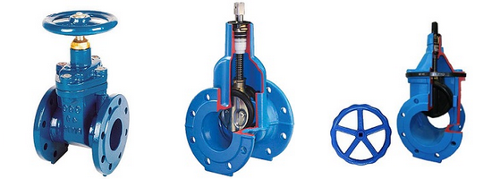
If the fluid head can reach 20 m, a non-return valve must be installed in the pipeline between the gate valve and the pump nozzle. The purpose of the non-return valve is to prevent the reverse movement of fluid in the event of a sudden stop of the pump and water hammer in the system. If the check valve breaks, the fluid flow is able to turn the shaft of the centrifugal pump in the opposite direction - this can lead to mechanical failure. It is also possible to idle, which will lead to overheating of the pump motor.
Centrifugal Pump Failures
If external conditions do not adversely affect the operation of the pump, the cause of the poor operation must be sought in the pump itself. Most often, the problems of centrifugal pumps are related to the condition of the seals. The good condition of the seals ensures a long and smooth operation of the pump. The rotation of the shaft with beats exerts an excessive load on the stuffing box, which reduces their service life. The cause of the beat can be a violation of the centering of the axis of rotation of the motor shaft, poor condition of the bearings. Bearings must be checked and lubricated regularly. Failure of the bearings can lead to failure of the entire pump.
It is not recommended to overtighten the fastening of the plate covering the glands. Too tight a clamp will reduce the flow of water droplets through the stuffing box, make it less wet, which in turn will worsen the quality of the seal. If the pump motor overheats due to different coefficients of thermal expansion of the parts, the stuffing box sleeve may fail. If not all sealing rings have been replaced in the stuffing box, then the remaining old dry and hard rings will reduce the efficiency of the stuffing boxes.
When operating pumps with violations of the operating rules and obsolete equipment, breakdowns occur. Also, equipment may fail due to the long service life.
The ideal option is to replace the broken centrifugal pump with a new one or return it to a service center if the breakdown is minor. But this is far from affordable for everyone. To save money, many repair pumps on their own.
1 Rules for the operation of centrifugal pumps
Due to the reliability of centrifugal devices, the need for repair and maintenance is rare. Failures occur due to non-compliance with service rules. These rules include:
- the device is operated only with liquid. Dry running wears shaft seal;
- lack of downtime of the mechanism. If there is no need for the apparatus to work, it must be started once a month. With prolonged periods, a simple shaft is oxidized;
- unit is used at positive temperature . Operation during frost leads to freezing of the liquid and breakage of the unit;
- operation in the passport mode. Work occurs at an average feed rate not exceeding the maximum efficiency indicator;
- timely servicing of oil seals. In the absence of lubrication, the shaft of the device fails.
1.1 Malfunctions of centrifugal pumps and their elimination
The signs of malfunction determine the cause of the breakdown.
Symptoms and solutions:
- After start-up, the unit does not supply water. The causes of failure in this case may be: incorrect start-up of the device (to eliminate it is necessary to restart the device after removing air); low wheel speed (increase the frequency to eliminate breakage); the air collector is not closed on the body of the device (it is worth closing the air collector); clogging of the intake valve (the valve is cleaned to eliminate); weakening of the gland (tighten the gland to eliminate).
- The connected device works, the shaft does not rotate. The causes of the breakdown are: the device is blocked due to prolonged shutdown (for repair, the shaft is scrolled with a screwdriver or manually, depending on power); a foreign body enters the flow part of the centrifugal pump (after removing the snail, a foreign object is removed and a filter is installed); problematic power supply from electricity (the correctness of the connection and the matching of consumed and rated power are checked).
- The device does not turn on. The cause of this failure may be a fuse fuse or a burnout of the winding (replacement of devices is necessary for repair).
- Noise during the operation of the device. There can be several reasons for this type of breakdown: the device is filled with air (bleed air and install a vent); fluid level below suction level (lower unit).
- A working device is accompanied by vibration. The reason is the poor attachment of the device (attach the device), the bearing of the centrifugal pump has worn out (the bearing should be replaced).
- Bearings are heating up. The reason is that centering of the shaft and the device is poor (do the alignment).
- Increased pressure at the outlet of the device. The cause of the breakdown is a high speed (reduce the speed or cut and shift the impeller).
- High power consumption. It is caused due to the high density of the liquid (the engine changes to a more powerful one); high resistance of the system (for repairs it is necessary to close the valves on the pressure hose).
- Lack of supply of the device. It arises due to air entering the system through the gland (it is necessary to tighten the seals, turn off the device and raise the liquid level in the device to normal); contamination of the intake valve or suction tube (to eliminate, you must disassemble the unit to clean the valve).
- High noise when starting a centrifugal pump. The reason is the lack of lubrication (lubricate the device); low-quality fasteners (tightly attach to the foundation); air getting into the device (the device turns off and it is again filled with liquid); low pressure (adjust the process of the device).
- After the start of work, the motor protection is turned on. The reason is electricity (the problem of resistance in the ground phase is eliminated).
2 Brief diagram of the repair of centrifugal devices
The sequence of repairs is as follows:
- the body of the device is washed outside;
- the device is disassembled;
- details are inspected, washed and cleaned;
- parts are removed, repaired or replaced;
- spare parts are completed;
- the device is going;
- breaks in and tested;
- the body is painted.
2.1 Repair and prevention of breakdowns of centrifugal pumps
Any centrifugal pump requires care and thoroughness during repair due to the complexity of the design . The basic rule of repair is disconnecting the device from the network before starting work.The stages of repair of centrifugal pumps consist of the following items:

- before repairing the device, it must be disassembled. Dismantling is carried out by removing the device housing. After disassembling the centrifugal pump with your own hands, it must be inspected;
- inspection and measurement of the clearances of the sealing parts and the rotor of the unit;
- bearing replacement;
- the shaft is checked for roughness and cracks. When identified, they change it;
- measuring the case for a deviation from the norm;
Such events are held to maintain the apparatus in good condition, so the frequency of such repairs is once every 4500 hours.
For global repair during the operation of 26000 hours, it is necessary to perform the following manipulations:
- shaft change;
- change of o-rings, bushings;
- replacement of sectional parts of the device;
- hydraulics test.
Repair of centrifugal pumps and their maintenance is a difficult task, so problems arise during its implementation. Such difficulties include:
- coupling removal. To perform the procedure, you must resort to the help of a puller;
- removing the pressure flange;
- removal of loose leaves;
- analysis of bearings;
- removal of impellers.

After repair work and replacement of necessary parts, it is necessary to assemble the device. The assembly sequence is as follows:
- Checking and preparing the parts to be installed.
- Fitting parts to their locations.
- Grinding and grinding in of placements of replaceable parts.
- When using a diameter wrench and observing the force, the screw fasteners are tightened.
- The impeller is assembled on the shaft, observing the axial clearance.
- Subject to perpendicularity, an unloading disk is installed to the end side.
After repair work, the mechanism is tested at a specialized stand. Tests consist of several points:
- short start and stop;
- warming up the device;
- operating mode test.
With a short start, lasting about three minutes, check the lubrication of the bearings, the correct readings and the rotation of the rotor.
Devices designed to work with hot liquids are warming up.
When testing the operating mode, they turn on the electric motor, open the valve after reaching the entire speed, the device is run in for two hours.
For a long service, your unit must be periodically given for scheduled repairs or to do it yourself. This event will lead to a decrease in the number of breakdowns. And making timely repairs, the device will last a long time.
Centrifugal pumps are the most common type, used as surface and submersible equipment. This is because they have a fairly simple design and relatively large performance.
But, unfortunately, like all equipment, pumps break down and require maintenance. Repair of centrifugal pumps should be carried out in a specialized service center, but in some cases, maintenance can be done independently and at home.
1 Centrifugal pump device
The name of the devices unites a large class of products, which, depending on the manufacturer and design, should be serviced differently. Accordingly, the options for failure and repair of the centrifugal pump of one subspecies have significant differences from the subspecies of the other.
In order to repair the water pump, while not reducing performance, you should clearly understand its structure, the presence of features. To do this, along with the documentation, a scheme and a list of components and spare parts are included in the product.
In the process of ascertaining the operation of pumping equipment, you can determine almost all the failures of centrifugal pumps.
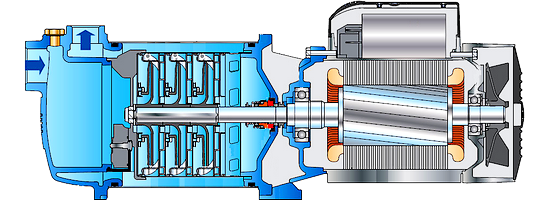
Powerful centrifugal pumps for lifting to high heights and supplying it with high pressure are drawn from sections. An example of such a sectional representative is a submersible submersible pump.
Centrifugal Pump Parts:
- responsible for the created pressure - the impeller - driven by the shaft of the electric motor, creates a centrifugal force to suck and push the water mass into the pipe of the supply and distribution pipe.
- driving the entire design of the pump - an electric motor, which by the way is also the drive of both internal and external cooling.
- containing the constituent elements - the housing - protects against damage in operation, installation / dismantling.
- auxiliary structural elements - seals, seals, bearings, bushings, thermal protection - directly affecting the correct, silent and high-quality operation of pumping equipment.
1.1 Organizational basis of the product
Fundamentally, when starting a centrifugal pump, the electric drive rotates the rotor shaft, on which the pump impeller with blades is fixed. Rotating, the structural element creates a centrifugal force, moving water between the blades and pressing it to the edges of the cylindrical chamber (glass). Under the influence of force, the fluid moves from the working chamber to the pipe of the common water supply system. In this case, a new portion of water comes from the supply pipe by creating suction vacuum at the pump inlet.
It should be understood that the presence of water at the inlet is necessary, since the pump does not work “dry”, since the fluid pumped through it is its main cooler. Without cooling, the structural parts will overheat and show incorrect operation right up to the failure. This is especially true for submersible pumpswhich is physically impossible to organize air cooling.
Air cooling is organized in the surface representatives of this type of equipment. In pumping devices, the drive motor is equipped with a fan impeller, which drives air flows directly over the housing surface, which additionally removes heat generated by the operation of the mechanism.
Feature centrifugal equipment is a recommendation to work with clean water without impregnations and impurities that may affect the functionality and duration of quality work. So large particles and sand can clog the inlet channels, the working chamber, block the impeller, which will invariably disable the pump or significantly affect the power of the outlet head. Reducing the number of such releases into the product will increase its life and simplify maintenance.
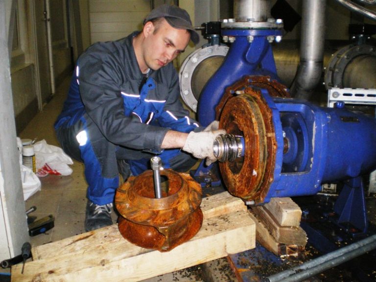
2 Centrifugal Pump Service
To reduce pump maintenance costs, a visual inspection of the entrusted equipment should be carried out at least twice a year. Breakage is easier to prevent than to fix it later.
For this:
- if the pump is submersible, take it to the surface. Perhaps this will be a rather difficult task and can not do without help, but in the future it will prevent even greater efforts.
- after lifting, it is necessary to inspect the mount and visually verify the integrity of the cable connections and the cabinet integrity, contamination and corrosive areas. If in doubt, be sure to check to avoid repeating the first paragraph again.
- the correct solution during the test is to start the device for a short period of time and listen - noise in operation will signal possible problems.
Work during the periodic inspection significantly delay the overhaul of centrifugal pumps with possible significant costs. The presence of sludge or sand on the pump will be the first signal of siltation of the water source and the need for action to clean or swell it. Failure to do so will result in equipment damage.
2.1 How to repair a centrifugal pump with your own hands?
Disassemble the connected pump is prohibited by the rules of the BEP and safety. Your device must be de-energized exactly, like all automation and protection belonging to it, and, only after making sure of this, start work.
Briefly, the repair process is described as follows:
- disassembly is carried out after pulling the pump out of the water on a clean, smooth surface so that there is no loss of connecting elements and parts of the structure. For reliability, sign / number all dismantled parts of the device. The whole process can be accompanied by photofixation or video filming;
- by visual inspection to detect worn-out elements and replace them first after purchasing from the manufacturer or dealer of the equipment. Only a fully compliant analogue will provide further safe operation;
- clean other components and, if necessary, apply lubricant;
- in the reverse order, assemble the equipment and check its operability. If the user has forgotten how to connect the pump back to the water supply system or to the mains, it is necessary to coordinate these actions with the schemes and recommendations of the instruction that are included in the kit.
3 Some pump breakdowns
Problems with centrifugal equipment are divided into:
- mechanical damage and deformation;
- management failures.
According to the statistics of equipment services, breakdowns are often caused by inept device users, as well as due to unattended technical inspections and equipment cleaning from pollution.
To mechanical belong defective breakdowns of the assembly, as well as wear of parts over time.
Defective product is detected almost immediately, possibly even when it is first included in the network. In this case, you should exchange the device under warranty from the seller.
If some elements are worn, the pump:
3.1 Gives low pressure, buzzes
A worn hose or supply pipe may be an elementary problem. But also this diagnosis is characteristic of a worn or displaced impeller.
To return the pump to the desired mode will help replace the repair kit, which includes seals and a worn element.
3.2 Overheating and vibrational movements
The simplest problem may be cavitation processes in the working chamber of the pump or simply airing. The disadvantage in the design is the inability to operate the pump without water, even a small period of time of such work can significantly damage the pump and disable it.
More difficult is the breakdown of the bearings of centrifugal pumps. With a working unit, the start and stop of the centrifugal pump are smooth, without any noise. If there is a problem, it is necessary to disassemble not only the pump compartment, but most likely the motor part.
After replacing the bearings, check all pump sleeve parts that could cause a problem and use the repair kit.
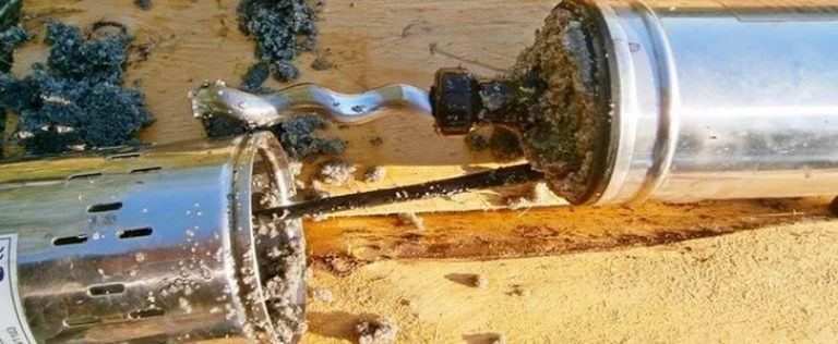
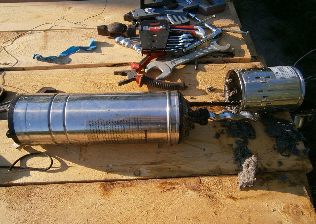
3.3 Wedge
Equipment can “catch a wedge” when large debris enters the hull, clogging the water and sand along the silt. To restore product functions, clean water passages and intakes.
If there is a worn-out structural element that impedes normal operation, it should be removed and replaced with a new one.
3.4 Fluid flow
In this case, sealing materials are clearly to blame and urgent replacement is needed. An excellent indicator of problem areas can be corrosion areas on the product body.
The control system malfunctions include:
- problematic power supply;
- operating mode without water;
- broken electric drive.
Defective insulation is the main cause of poor contact, damage to the wire and failure of the pump unit.
To avoid working without water, special level control sensors are installed, which help turn off the pump in dangerous positions. Their failure leads to damage to the drive.
A non-working drive motor is a complex breakdown that service workers can help solve or an excuse to buy a new centrifugal pump.
3.5 Repair of a household centrifugal pump BTsNM (video)
Malfunctions of centrifugal pumps and their maintenance
Malfunctions (failures) arising in pumping units and water lines, lead to disruption of their performance, reduce the efficiency of extinguishing fires and increase losses from them. Failures in the operation of pumping units arise due to a number of reasons:
firstly, they may appear due to incorrect actions of drivers when turning on water communications; the probability of failures for this reason is the less, the higher the level of combat training of combat crews;
secondly, the cause of failures is wear of the working surfaces of the parts; failures for these reasons are inevitable (you need to know them, evaluate their occurrence in a timely manner);
thirdly, the cause of failures is a violation of the density of the joints and the associated leakage of liquid from the systems, the inability to create a vacuum in the suction cavity of the pump (you need to know the causes of these failures and be able to eliminate them).
Malfunctions of pumping systems PN. Symptoms of possible malfunctions leading to failures, their causes and remedies are given in Table 2.4.
Table 2.4.
| Symptoms | Causes of malfunctions | Remedies |
| When the vacuum system is turned on, a vacuum is not created in the cavity of the fire pump. The fire pump does not fill with water when the vacuum is too high. The vacuum meter does not show pressure (vacuum) when the pump is working. There is a knock and vibration when the fire pump is operating. The fire pump first supplies water, then its performance decreases. The pressure gauge’s arrow fluctuates greatly. The fire pump does not create the necessary pressure. The foam mixer does not feed the blowing agent. The gas siren is working poorly, the sound is attenuated. The gas siren is working after switching off. The monitor of the fire monitor and the valve of the water supply lines do not open when opening the taps on the column. | Air suction: a) the drain valve of the suction pipe is open, the valves are loose on the valve seats and valves, valves and valves are not closed; b) leaks in the connections of the vacuum valve and pump, the glass of the diffuser of the foam mixer, pipelines of the vacuum system, oil seals of the pump, plug valve 1. Large suction height. 2. The fire suction hose is stratified. 3. The suction net is clogged. 1. Defective pressure gauge. 2. The channel of the vacuum gauge is clogged or the water is frozen 1. There is cavitation. 2. Loosen the bolts securing the pump to the frame. 3. Worn ball bearings. 4. Foreign objects getting into the pump 1. There are leaks in the suction line, delamination of the sleeve, and the suction net is clogged. 2. Impeller channels clogged. 3. Leaks in the seals of the fire pump. 1. Impeller channels are partially clogged. 2. High wear of the o-rings. 3. Air leaks. 4. Damage to the impeller blades. 1. The pipe from the tank to the foam mixer is clogged. 2. Clogged dispenser holes. 1. The channels of the gas distributor and the resonator are clogged. 2. The exhaust pipe does not completely block the shutter. 1. The damper spring is loose or broken. 2. Traction length is adjusted. 1. Low air pressure in the brake system. 2. Leaky connections of valves, taps, pipelines. 3. Defective stop valve. | a) Close all valves, valves, gate valves. If necessary, disassemble them and fix the malfunction. b) Check the tightness of the joints, tighten the nuts, if necessary, replace the gaskets. If the pump seals are worn, replace them 1. Reduce the suction height. 2. Replace the suction sleeve. 3. Clean the suction strainer. 1. Replace manovacuum meter. 2. Clean the channel of the manovacuum meter. 1. Reduce suction lift or water flow. 2. Tighten the bolts. 3. Replace ball bearings. 4. Remove foreign objects from the cavities of the pump wheel 1. Find the leaks and repair, replace the sleeve, clean the net. 2. Disassemble the fire pump, clean the channels. 3. Screw on the grease fitting cover, replace the oil seals. 1. Disassemble the pump, clean the channels. 2. Disassemble the pump, replace the rings. 3. Eliminate air leaks. 4. Disassemble the pump, replace the wheel. 1. Disassemble, clean the pipeline. 2. Disassemble the dispenser, clean its holes. 1. Clean the channels and resonator. 2. Adjust the traction length. Disassemble, clean the shutter. 1. Replace spring. 2. Adjust traction. 1. To increase the pressure of the engine. 2. Tighten the union nuts, replace the gaskets. 3. Disassemble, fix. |
Faults in the pumping station monitoring station. Symptoms of possible malfunctions leading to failures, their causes and remedies are given in table 2.5.
Table 2.5
| Symptoms | Causes of malfunctions | Remedies |
| 1. The vacuum pump does not turn on. 2. The vacuum pump is working, insufficient vacuum. 3. The vacuum pump is working, the vacuum is normal, water does not enter the pump. 4. The vacuum pump does not turn off at an outlet pressure of more than 0.4 MPa (4 kgf / cm 2) (at the PTsNV 20/200 - 1.2 MPa). 5. When the pump is in operation, the vacuum pump is frequently turned on and off. At PTsNV 20/200 (optional) 6. During pump operation, flow rate decreased, outlet pressure is below normal 7. During pump operation, knocks and vibration are observed. 8. The pump shaft does not spin. 9. Water flows from the drainage compartment of the pump. 10. Do not rotate the handle of the dispenser. 11. High oil consumption in the oil bath of the shaft bearings. 12. The pump shaft rotates, the tachometer needle is at zero. 13. * When the ejector is on and the dispenser is open, the foaming agent does not enter the pump. 14. During the operation of the foam mixer, the pump is not supplied to the pump or its dosage level is insufficient. 15. If there is no feed, the “no feed” indicator does not light. 14. When the ASD is turned on, the “ASD power” indicator does not light, the dispenser handle does not move. 15. When the ASD is turned on, the dispenser handle does not move, the “ASD POWER” indicator lights up 16. When the foaming agent is dosed in automatic mode, the foam quality is unsatisfactory, the dispenser handle does not reach the position corresponding to the number of foam generators working. 17. The increased consumption of the foaming agent during dosing in automatic mode, the dispenser handle stops in a position corresponding to a larger number of foam generators than is actually connected. 18. When dispensing the foaming agent in the automatic mode, the dispenser handle reaches the stop (position “5-6%”), and the “ASD norm” indicator does not light up, and the dispenser motor continues to rotate. 19. The running hours counter does not work. | 1. Wear on the rubberized pulley of the vacuum pump drive. 1. Air leaks: a) in the suction line; b) through open drain taps; c) through the oil tank (in the complete absence of oil); d) through damaged vacuum pipelines. 2. Pulley slippage due to: a) oil getting on the friction surface; b) insufficient pulley pressure. 3. Inadequate lubrication to the vacuum pump. 4. Faulty non-return valve — stuck or loose fitting to the seat. 1. The suction net is clogged. 2. Stratification of the suction hoses. 1. Large clearance "D" between the stem of the shut-off mechanism and the lever. 2. A large force pressing the pulleys of the drive of the vacuum pump. 1. Disruption of pressure as a result of insufficient deepening of the suction grid. 2. Disruption of pressure as a result of malfunction of the vacuum shutter (valve jamming). 3. Disruption of pressure as a result of untimely actuation of the vacuum shutter due to depressurization of the control hydraulic actuator. 1. The suction net is clogged. 2. The protective screen at the pump inlet is clogged. 3. The pump flow exceeds the permissible suction height. 4. Impeller channels are clogged. 1. Loosen the pump mounting bolts. 2. Worn pump bearings 3. Foreign objects enter the pump cavity. 4. The impeller is damaged. 1. In the summer period - blockage of the pump. 2. In the winter - freezing of the impeller and seals 1. Violation of the tightness of the shaft end seal. 1. The appearance on the friction surfaces of crystalline deposits and corrosion products as a result of poor washing. 1. Wear on rubber cuffs. 1. Open circuit of the tachometer. 1. Dispenser shut-off valve does not work due to clogging of the piping supplying water to the valve control bellows. Additionally at PTsNV 1. Depressurization of the vacuum control system drive. 2. Jamming of the spool in the foam mixer valve or clogging of its cavity as a result of poor flushing. 1. Open circuit power. 2. The LED (lamp) has burned out. 3. Jamming of the falling valve in the guide 4. Faulty magnet-electric contact 1. Open circuit in the power supply circuit “fire truck - electronic unit”. 3. Inadequate clutch of the friction clutch of the dispenser drive 1. Open circuit in the electric circuit "electronic unit - electric motor" of the dispenser 2. Inadequate clutch of the friction clutch of the dispenser drive 1. High rigidity of the water supplied by the pump. 1. Contamination of the electrodes of the foam concentration sensor. 1. The dispenser shut-off valve does not open due to clogging of the piping supplying water to the valve control bellows. 2. If the malfunction appears only when working with a large number of GPS-600 (4-5 pcs.), The reason is an increase in the hydraulic resistance of the blowing agent line as a result of its clogging. 3. Open circuit of the "electronic unit - concentration sensor" 1. An open circuit of the power supply between the primary blowing agent and the electronic unit or between the electronic unit and the indicating device on the panel. 2. Faulty electronic unit 3. Faulty operating time counter. | 2. Adjust the clearance “D” between the pusher of the shut-off mechanism and the stop of the bracket for the vacuum pump (1.5 ... 2 mm). When the rubber is completely worn out (the protrusion of the rubber behind the metal rim is less than 0.5 mm), replace the pulley. 1. Check the connecting heads of the suction hoses, detect and repair leaks in the pump, fill the oil tank. a) degrease the pulleys with gasoline and dry b) adjust the clamping force 3. Check the oil flow rate and the condition of the oil line, if necessary, flush the oil line and adjust the oil consumption. 4. Detect and troubleshoot a falling valve. Before eliminating the malfunction, take water with the valves closed. 1. Clean the suction strainer. 2. Replace faulty sleeves 1. Adjust clearance. 2. Adjust the pulley pressure. 1. Ensure that the suction net is immersed to a depth of at least 300 mm. 2. Correct the vacuum shutter malfunction; before eliminating the malfunction, it is allowed to use a vacuum valve as a vacuum shutter - manually close when the outlet pressure appears in the range from 2.5 kgf / cm 2 to 3.5 kgf / cm 2. 3. Check the liquid level in the hydraulic drive. Establish leaks, eliminate them. 1. Check the suction net. 2. Check the integrity of the suction screen, if necessary, clean the protective screen at the pump inlet. 3. Reduce feed (number of working trunks or speed). 4. Clean the channels 1. Tighten the bolts. 2. Replace worn bearings with new ones. 3. Remove foreign objects. 4. Replace the impeller. 1. Clean the inside of the pump. 2. Warm up the pump with warm air or hot water. 1. Replace worn parts (assemblies) of the end seal 1. Disassemble the dispenser, clean the mating surfaces from plaque. 1. Replace the cuffs. 1. Detect and repair open circuits. 1. Clean the pipe (duct). 20/200 1. Locate leaks due to fluid leakage, repair leaks, check the diaphragm of the vacuum shutter. 2. Disassemble the foam mixer valve and clean its cavity and parts from contamination. 1. Detect and eliminate. 2. Replace the LED (lamp). 3. Identify the causes and eliminate jamming. 4. Replace magneto-electrical contact. 1. Detect and repair open circuit. 2. Adjust the coupling in accordance with clause 9.2. 1. detect and eliminate open circuit 2. adjust the couplings 1. Using a corrector, increase the concentration of the foaming agent or switch to manual dosing (see. 7.4). 1. Clean the electrodes of the concentration sensor. 1. Clean the pipe (duct). 2. At the next MOT, clean the frother line, including the dispenser cavity. 3. Detect and repair open circuit. 1. Detect and repair open circuit. 2. Replace or repair the electronic unit. 3. Replace the counter. |
The PTsNV 4/400 pump does not have a suction system, but its design has two valves: a bypass valve and a shut-off valve. Faults in them are a violation of the normal operation of the pump. Their list is given in table 2.6.
Table 2.6.
| Symptoms | Causes of malfunctions | Remedies |
| 1. Water flows from the drain hole of the pump. 2. When the pump is running, its housing is very hot. 3. The supply has decreased, the pressure in the pressure head manifold is normal. 4. When the ejector is turned on and the dispenser and spray gun are open, the foaming agent does not enter the pump 5. The dosage level of the foaming agent is below normal. | 1. Violation of the tightness of the end seal. 1. Closed bore holes in the bypass and shut-off valves. 1. Jamming of the bypass valve. 1. Bypass valve defective. 2. Jamming of the shut-off valve. 1. Clogging of the line of the foaming agent, in particular, the flow cavity of the shut-off valve. | 1. Disassemble the pump, replace worn seal parts. 1. To remove valves, to sort and eliminate malfunctions. 1. Remove the valve, eliminate the malfunction. 1. Remove the valves, eliminate the detected malfunctions. 1. Disassemble and clean all elements of the frother line. |
Other malfunctions may occur in the PTsNV 4/400 pump, but in most cases they are similar to malfunctions of other pumps of this series.
Technical maintenance (MOT) of pumping units. Maintenance is a set of operations to maintain the operability or serviceability of products when used for their intended purpose. In GPS, a series of maintenance is carried out: daily maintenance (ET), maintenance-1 and maintenance-2 after the total mileage of a fire truck, equal to 1,500 and 7,000 km, respectively. In addition, their service in the fire and after the fire.
MOT on fire. Periodically check the tightness of the pump unit for water leakage through connections and seals.
On PM pumps, after every hour of operation, lubricate the oil seals through a cap grease fitting.
Maintain a positive temperature in the pump compartment.
On the monitoring station pumps, control the water supply and prevent overheating of the pump.
THEN after the fire. Drain the pump. In winter, remove water from the tube connecting the PN to the gas-jet vacuum apparatus by briefly turning it on.
After extinguishing the fire with foam, rinse with water the foam supply system and pump.
Regulated work maintenance are given in table 2.7.
Table 2.7
| PN-40UV | PTsNN-40/400 and PTsNV 20/200 | PTsNV 4/400 | ||
| ETO | 1. Check the operation of taps and valves, the integrity of communications and the oil level in the crankcases 2. Check the performance of vacuum systems (leak test) 2. - "- 3.Clean the mesh at the pump inlet | |||
| TO-1 | 1. Perform the scope of the ETO | |||
| 2. Check the condition and controllability of the drive of the vacuum apparatus from the pump room 3. Disassemble the foam mixer and clean it, check the condition of the taps 4. Check the mounting of the pump | 2. Check the tightness of the fastenings of all units. 3. Check the condition of the drive elements of the vacuum pumps. 4. Check the performance of the vacuum pump. 5. Change the oil in the oil baths of the shaft bearings. | 2. Check the operation of the bypass valve. | ||
| TO-2 | 1. Perform the scope of work TO-1 | |||
| 2. Check the technical condition of the pump and the dosage level of the foaming agent. 3. Check the performance of instrumentation. | 2. Lubricate the screws on the pressure valves. 3. Check the foaming agent dosing level and clean the pump foam lines (if necessary) | 2. Change the oil in the oil baths of the shaft bearings. |
Literature
Lecture 13. Fire hoses
A set of fire-technical weapons for supplying fire extinguishing substances to the fire consists of fire hoses and hydraulic equipment. Its use allows you to form the pump-hose system of a fire truck (motor pump) in order to ensure the supply of fire extinguishing substances. The elements that make up the PTV kit are the most commonly used fire fighting equipment. Knowing their technical characteristics and devices will improve the efficiency of the use of pumping-hose systems of fire engines (motor pumps) in the elimination of fires.
Fire hoses are flexible pipelines equipped with fire connection heads and designed to transport fire extinguishing substances.
Fire hoses classification. Water for extinguishing fires is supplied by pumps of fire engines and motor pumps from various water sources. The simplest water supply scheme is to take it from the tank of a fire truck and pump it through the trunk 1 and working 3 hose lines to the trunks 4. Fire hoses through which fire extinguishing agents are supplied under pressure are called pressure pipes. In the case of using open water sources, suction hoses are used for water intake. When sucking water from the water supply network, a pressure-suction hose 6 and a short pressure hose 8 are used.
With sufficient pressure in the water supply network, water enters the pump along the hoses 6 and 8. In case of insufficient pressure, it is absorbed by the pump along the pressure-suction hose 6.
Suction hoses. Suction hoses of classes “B” (working medium - water) and “KShch” (working medium — weak solutions of inorganic acids and alkalis) are used to complete fire engines and motor pumps, depending on the working conditions, they are divided into two groups: 1 — suction - for work during rarefaction and intake of water from open water sources; 2 - pressure-suction - for work under pressure and under vacuum.
They consist of an inner rubber chamber 3, two textile layers 2 and 6, a wire spiral 4, an intermediate rubber layer 5 and an outer textile layer 1.
Rubber layers provide air and water tightness to the sleeve, as well as elasticity and flexibility. The wire spiral 4 increases the mechanical strength and eliminates the flattening of the sleeve under atmospheric pressure. At the ends of the suction hoses there are soft (without spirals) cuffs for attaching the hoses to the heads, connecting suction 7 with annealed galvanized wire, diameter 2.0 - 2.6 mm or metal galvanized collars.
On the outer surface of the cuff of each sleeve, a marking is applied containing the name of the manufacturer, standard number, group, type, inner diameter, working pressure (for sleeves of the 2nd group), length and date of manufacture.
Technical characteristics of the suction hoses used on mobile fire fighting equipment are presented in Table 3.1.
Table 3.1
The length of the suction hoses is determined by the design feature of fire trucks. A case for storing suction hoses is usually located on the superstructure of a fire truck and has a length of more than 4 meters. The design of the case provides drying of the suction hoses by blowing when the fire truck is moving.
Suction hoses received at the fire department or at the hose base are subject to incoming inspection. In this case, the presence and marking data is checked first of all. The sleeves that have passed the incoming inspection impose connecting suction heads on the heads, after which they are subjected to leak tests at hydraulic pressure and vacuum. Having created a pressure of 0.2 MPa, it is held for 10 minutes. On the sleeve there should be no tears, local swelling, deformation of the metal spiral. Under a vacuum of 0.08 MPa, the sleeve can withstand 3 minutes, while the vacuum drop should not exceed 0.013 MPa. When tested, there should be no flattening and kinks. Suction hoses located on fire engines are tested during the TO-1 of the vehicle.
Pressure hoses They are designed for transportation of extinguishing agents under excessive pressure and can be used both for the assembly of fire hydrants and portable motor pumps (working pressure 1.0 MPa), and mobile fire fighting equipment.
The design of the pressure hose can consist of the following elements: a reinforcing frame (cover), an internal waterproofing layer and an outer protective layer. Reinforcing frames of pressure hoses are woven or knitted from threads of natural (linen, cotton, etc.) or artificial (lavsan, kapron, etc.) fibers. The reinforcing frame is formed by interlacing threads at an angle of 90 0. Longitudinal threads are called warp and cross threads are called weft.
According to the climatic modification, the pressure hoses can be of two types. Executions "U", designed for operation at an ambient temperature from - 40 0 \u200b\u200bС to + 45 0 С and designs "UHL", designed for operation at an ambient temperature from - 50 0 С to + 45 0 С.
On mobile fire fighting equipment, pressure hoses with a length of 20 ± 1 m and a diameter of 51, 66, 77, 89, 150 mm are used.
Fire pressure hoses must have high strength, good resistance to abrasion, sunlight, putrefactive processes, aggressive environments, low and high temperatures. Hydraulic resistance to water flow should be as small as possible, in addition, a number of ergonomic requirements are imposed on them: lightness, small dimensions of the rollers, elasticity.
Natural fiber pressure hoses are of limited use. Dry clean linen sleeves are relatively light, and their rolls are small. When water is supplied through such sleeves, the outer surface of the cover fabric is moistened by seeping water through the cover walls (percolation). This increases the heat resistance of linen sleeves in fire conditions. However, the increased tendency of linen sleeves to putrefactive processes, large hydraulic losses, as well as the difficulty of operation at low temperatures limit their scope in fire engines.
Pressure hoses with a reinforcing frame made of synthetic fibers have several design options.
The device rubberized sleeve, related to the type of pressure hoses with an internal waterproofing layer without an outer coating of the frame. Such a sleeve has a reinforcing frame 1 made of synthetic fibers. As an internal waterproofing layer 2, a rubber chamber is used, which is inserted into the reinforcing cage 1, pre-lubricated with rubber glue 3 and vulcanized with steam at a pressure of 0.3 ... 0.4 MPa at a temperature of 120 ... 140 0 C for 40 ... 45 min.
The design of the latexed sleeve is shown in Fig. 3.5. It refers to the type of pressure hoses with an internal waterproofing layer and with the impregnation of the reinforcing cage with the same material as the waterproofing layer. Reinforcing frame 1 latexed sleeves are made of synthetic fibers. Such a sleeve has an inner waterproofing layer 2 made of latex film. In addition, the reinforcing frame is impregnated with a solution of latex, which forms the outer latex film 3, acting as a protective layer.
Two-layer hoses with internal waterproofing 2 and external protective 3 coating have several advantages compared to other types of hoses. The inner waterproofing layer 2 provides minimal hydraulic losses for the flow of extinguishing agent, and the outer protective layer 3 protects the fabric of the reinforcing frame 1 from abrasion, exposure to sunlight. This increases the reliability and durability of the sleeves.
The type of sleeves with double-sided coating include pressure hoses with double-sided polymer coating and pressure hoses with a working pressure of 3.0 MPa.
Technical characteristics of pressure head fire hoses for mobile fire fighting equipment are described in NPB 152-2000, some of which are presented in Table 3.2.
Table 3.2
Fire pressure hoses with a diameter of 77 mm and more are used for laying trunk lines, and with a diameter of 51 and 66 mm - working hose lines.
Parameters of technical characteristics of pressure hoses largely determine the effectiveness of fire departments. So, the roughness of the inner surface of the sleeves affects the loss of water pressure in the hose line and regulates the maximum possible length of this line.
In pressure hoses, when water is supplied, their length and cross-sectional area change. The inner waterproofing layer of the sleeve under the pressure of water is pressed into the reinforcing frame (cover) of the sleeve. In this case, a roughness profile is formed on its inner surface, which determines the value of resistance to water flow. For sleeves 20 m long, the resistance coefficients S p specified in Table 3.3 are determined.
Table 3.3
The pressure loss in the main hose line can be determined by the formula
h m rl \u003d N p · S p · Q 2, m (3.1)
where S p - resistance coefficient of one sleeve 20 m long (see table 3.3); Q - water flow in the main line, l / s; N p - the number of sleeves in the trunk line, pcs., which is defined as
N p \u003d 1.2 · L / 20, pcs.(3/2)
where L - distance from the fire truck to the place of supply of trunks, m
The length of any hose line depends primarily on the hydraulic resistance of the sleeves S p and flow Q feed water. So, the maximum length of the main hose line can be determined by the formula
l ol \u003d, m(3.3)
where Z m - the highest elevation (+) or descent (-) of the terrain at the maximum distance, m; Z ol - the greatest height of rise (+) or descent (-) of extinguishing devices, m.
Defining parameter in technical specifications of pressure hoses is its internal diameter, on which the mass of the roll of the sleeve (see table 3.2), the working pressure, and hydraulic characteristic hose line. Figure 3.7 shows the dependence of the pressure loss in one sleeve of the trunk line (20 m long) depending on the water flow. It is shown how the diameter of the sleeves affects the pressure loss in the line.
Sleeves are also distinguished by thermophysical characteristics. From his analysis it follows that latexed sleeves have the best heat-insulating ability. They have a lower value of the coefficient of thermal conductivity of the material λ at low temperatures. This means that when water is supplied at low temperatures, its cooling in the line of latexed hoses will be less intense compared to other types of hoses. The likelihood of icing of such a hose line is reduced.
The above parameters of pressure hoses should be taken into account when choosing them for specified operating conditions.
The pressure hoses, which entered the fire department or the hose base, are imposed on the connecting heads with soft galvanized wire with a diameter of 1.6 ... 1.8 mm after incoming inspection (for hoses with a diameter of 150 mm and a diameter of 2.0 mm). After that, the sleeve is marked with accessories for the hose base or fire department. On sleeves operated on hose bases, their serial number is marked. On the hoses belonging to the fire department, the marking consists of fractions, where the fire station number is indicated in the numerator and the serial number of the hose in the denominator. Further, the hoses are subjected to hydraulic tests under a pressure of 1.0 MPa. Sleeves for an operating pressure of 3.0 MPa are tested at the operating pressure of the high-pressure pump.
Sleeves that have passed hydraulic tests are sent to the dryer and transferred for operation. Passports are added to new sleeves. Sleeves in operation are tested after each maintenance and repair, as well as twice a year during seasonal maintenance of fire fighting equipment.
LITERATURE:
1. The combat charter of the fire brigade. - M.: Ministry of Internal Affairs of the Russian Federation, 1996. - 46 p.
2. Manual technical service. - M. - Ministry of Internal Affairs of the Russian Federation, 1996. - 170 p.
3. Means of providing rescue operations. Issue 4. - M .: VNIIPO Ministry of Internal Affairs of the Russian Federation, 1999 .-- 148 p.
4. Fire safety standards. VNIIPO, approved by order of the GUGPS of the Ministry of Internal Affairs of the Russian Federation, 1996. - 2000.
5. Brushlinsky N.N. Modeling the operational activities of the fire service. - M .: Stroyizdat, 1989 .-- 96 p.
6. Bezborodko M. D. and other fire equipment. - M.: VIPPSH of the Ministry of Internal Affairs of the USSR, 1989 .-- 236 p.
7. Yakovenko Yu.F., Zaitsev A.I. and other. Operation of fire fighting equipment. - M .: Stroyizdat, 1991 .-- 414 p.
8. Volkov V.D., Erokhin S.P. and others. Reference manual for work on special fire trucks. - M.: VNIIPO, 1999 .-- 236 p.
9. Bezborodko M.D., Brezhnev A.A. and others. Labor protection of firefighters. Modern requirements. - M .: Stroyizdat, 1993 .-- 184 p.
10. Technical descriptions and operating instructions for fire fighting equipment: JSC "Pozhtekhnika" Torzhok; AMO ZIL Moscow; Vargashinsky plant of fire and special equipment, Vargashi.
11. Yakovenko Yu.F., Kuznetsov Yu.S. Technical diagnostics of fire trucks. - M.: Stroyizdat, 1984. - 288 p.
12. Technical operation of cars // Ed. Doctor of Technical Sciences, Professor Kuznetsov U.S. .. - M.: Transport, 2000. - p.