The size of the well rings. Gost standards for reinforced concrete well rings
STATE STANDARD OF THE USSR
CONCRETE CONSTRUCTIONS
AND REINFORCED CONCRETE FOR WELLS
SEWER, WATER
AND GAS NETWORKS
SPECIFICATIONS
GOST 8020-90
STATE BUILDING COMMITTEE OF THE USSR
Moscow
STATE STANDARD OF THE USSR
Date of introduction 01.07.90
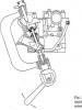
This standard applies to concrete and reinforced concrete structures made of heavy concrete and intended for the construction of round wells in underground pipelines of sewer, water and gas pipelines.
Designs are used in accordance with the instructions of the working drawings of a particular pipeline.
1. TECHNICAL REQUIREMENTS
1.1 . Designs should be made in accordance with the requirements of this standard and technological documentation approved by the manufacturer according to the working drawings of the series 3.003.1-1 / 87 and 3.900.1-14.
(Amendment)
1.2 . Key parameters and dimensions
1.2.1 . Designs are divided into types:
KFK - a working chamber of a well of household (fecal) sewage;
KDK - the same as intra-quarter networks;
KLK - the same storm storm;
KLV - the same, storm sewer, water intake;
KVG - the same, water and gas networks;
KS - wall ring of the working chamber or the neck of the well;
KO - support ring;
PO - base plate;
PD - road plate;
PN - bottom plate;
PP - floor slab.
1.2.2 . The shape and main dimensions of the structures of the wells must comply with those specified in .
In cases provided for by the working drawings of a particular pipeline, structures may have embedded products, as well as niche openings and cutouts that differ in location and size from those adopted in the working drawings of series 3.003.1-1 / 87 and 3.900.1-14.
(Amendment)
1.2.3 . The consumption rates of concrete and steel on the structure of the wells must comply with those specified in the working drawings for these structures.
1.2.4 . Floor slabs are divided into groups according to bearing capacity, depending on the depth of the slabs and the load on the surface of the soil backfill according to the instructions of the working drawings.
1.2.5 . Designs are marked with marks in accordance with the requirementsGOST 23009 . A design brand consists of alphanumeric groups separated by hyphens.
In the first group, the design size is given. The letters indicate the type of construction, the numbers before the letters indicate the serial number of the size (if necessary), the numbers after the letters (rounded to the nearest whole number) indicate (in decimeters):
for working chambers and support rings - their inner diameter;
»Bottom plates and ceilings - the inner diameter of the wells;
"Wall rings - their inner diameter and height;
»Base and road slabs - hole diameter.
In the second group for floor slabs indicate the group by bearing capacity.
In the third group for floor slabs or in the second group for other structures, indicate:
for structures operated under aggressive environmental conditions, - the permeability index of concrete, denoted by a capital letter: H - normal permeability, P - low permeability, O - particularly low permeability;
additional design characteristics (the presence of embedded products, holes, niches and cutouts) indicated in the mark in Arabic numerals or letters.
Example symbol (brands) of the working chamber of the KFK type with an internal diameter of 1250 mm:
KFK13
The same, wall ring with an inner diameter of 2500 mm, a height of 1190 mm:
KC25.12
The same, floor slabs, overlapping the well, with an inner diameter of 2000 mm, with a hole with a diameter of 1000 mm (size 2PP20), the second group in bearing capacity:
2 PP20-2
Note It is allowed to accept designations of brands of structures in accordance with the working drawings for these structures until they are reviewed.
1.3 . Specifications
1.3.1. Designs must meet the requirements of GOST 13015.0:
strength, stiffness and crack resistance; while the requirements for testing structures by loading do not show;
in terms of actual concrete strength (at design age and tempering);
frost resistance and water resistance of concrete;
by the thickness of the protective layer of concrete to reinforcement;
to steel grades for reinforcing and embedded products, including for mounting loops;
corrosion protection.
1.3.2 . Structures should be made of heavy concrete according toGOST 26633 classes or brands of compressive strength specified in the design drawings of structures.
1.3.3 . The normalized tempering strength of concrete is taken equal to 70% of the class or grade of concrete in terms of compressive strength.
The specified normalized tempering strength of concrete can be reduced or increased in accordance with the requirements of GOST 13015.0.
1.3.4 . The water absorption of concrete structures must comply with the established design documentation for a particular structure or specified when ordering structures.
1.3.5 . For reinforcing structures, reinforcing steel of the following types and classes is used:
thermomechanically hardened core classes of At-III C and At-IV C according to GOST 10884;
hot-rolled rod grades A-I, A-II and A-III according to GOST 5781;
reinforcing wire of class Bp-I according to GOST 6727.
1.3.6 . The shape and dimensions of reinforcing and embedded products and their position in the structures must correspond to those indicated in the working drawings.
1.3.7 . Welded reinforcing and embedded products must meet the requirementsGOST 10922.
1.3.8 . In the cases provided for by the working drawings of wells, running brackets should be installed inside the wall rings, located along the height of the ring after 300 mm and protruding 120 mm from the inner surface of the rings.
Running braces should be made of reinforcing steel of classes A-I and A-II according to GOST 5781.
By agreement between the manufacturer and the consumer, wall rings are allowed to be made without running brackets, provided that they are installed at the construction site.
1.3.9 . Running brackets must be protected against corrosion according to the instructions of the working drawings of the wells.
1.3.10 . Values \u200b\u200bof the actual deviations of the geometric parameters of the structures should not exceed the limits indicated in the table. .
Table 1
mm
|
The name of the geometric parameter |
Prev off |
|
|
Deviation from the linear size |
Height (thickness) of the structure: |
|
|
± 5 |
||
|
± 8 |
||
|
± 10 |
||
|
st. 1000 to 1600 |
± 12 |
|
|
± 15 |
||
|
± 20 |
||
|
The inner diameter of the working chambers, wall and support rings, the outer diameter of the floor slabs and the bottom, the diameter of the manholes and openings for pipelines: |
||
|
± 6 |
||
|
st. 1000 to 1600 |
± 8 |
|
|
± 10 |
||
|
± 12 |
||
|
Length and width of base and road slabs |
± 10 |
|
|
Position of holes and cutouts |
||
|
Deviation from flatness of the bottom surface of floor slabs (when measured from a conventional plane passing through three points) |
Outer diameter of floor slabs: |
|
|
st. 1000 to 2500 |
||
1.3.11. Requirements for the quality of surfaces and the appearance of structures are in accordance with GOST 13015.0. At the same time, the quality of the surfaces of structures (except for butt surfaces) must satisfy the requirements established for category A6. The surfaces forming the joint of structures that are monolithic at the construction site are subject to the requirements established for category A7.
By agreement of the manufacturer with the consumer, it is allowed to submit to all surfaces of the working chambers, wall and support rings the requirements established for category A7.
1.4 . Completeness
1.4.1. Working chambers are supplied to the consumer complete with floor slabs.
1.5 . Marking
1.5.1 . Design marking - byGOST 13015.2 . Marking is applied to the outer side surface of structures.
2. ACCEPTANCE
2.1 . Acceptance of structures - byGOST 13015.1 and this standard. In this design accept:
according to the results of periodic tests - in terms of frost resistance, water tightness and water absorption of concrete;
according to the results of acceptance tests - according to indicators of concrete strength (class or grade for compressive strength and tempering strength), compliance of reinforcing and embedded products to working drawings, strength of welded joints, concrete protective layer thickness to reinforcement, accuracy of geometric parameters, concrete surface quality .
Structures are accepted for strength, stiffness and crack resistance according to a set of standardized and design indicators in accordance with the requirements of GOST 13015.1.
2.2 . Acceptance of structures in terms of accuracy of geometric parameters, the thickness of the protective layer of concrete to reinforcement, surface quality is carried out according to the results of selective control.
2.3 . In the document on the quality of designs forGOST 13015.3 in addition, concrete grades on frost resistance and water resistance of concrete should be given (if these indicators are specified in the order for the manufacture of structures).
3. CONTROL METHODS
3.1 . The strength of concrete structures is determined byGOST 10180 on a series of samples made of concrete mix of the working composition and stored in the conditions establishedGOST 18105.
When tested by non-destructive methods, the actual compressive strength of concrete should be determined by the ultrasonic method according to GOST 17624 or by mechanical action devices according to GOST 22690, as well as by other methods provided by the standards for concrete test methods.
3.2 . The frost resistance of concrete is determined byGOST 10060 on a series of samples made from concrete mixture of the working composition.
3.3 . The water resistance of concrete is determined byGOST 12730.0 and GOST 12730.5.
3.4 . Water absorption of concrete is determined byGOST 12730.0 and GOST 12730.3.
3.5 . Welded reinforcing and embedded products are controlled byGOST 10922 and GOST 23858.
3.6 . The dimensions and position of reinforcing and embedded products, as well as the thickness of the protective layer of concrete to the reinforcement, are determined byGOST 17625 or GOST 22904.
3.7 . The dimensions, deviations from the flatness of the structures, the width of the surface technological cracks, the dimensions of the shells, flows and chips of concrete structures are checked by the methods establishedGOST 26433.0 and GOST 26433.1.
3.8 . Dimensions of structures are checked as follows:
the outer and inner diameters of the working chambers, wall and support rings, floor slabs and bottoms are measured by two mutually perpendicular diameters;
the thickness of the walls of the working chambers and wall rings is measured in four places at two mutually perpendicular diameters;
the height of the working chambers and wall rings is measured by four generators in two diametrically opposite sections;
the thickness of the plates and the support ring is measured in four places in two mutually perpendicular directions.
4. TRANSPORTATION AND STORAGE
4.1 . Transportation and storage of structures - byGOST 13015.4 and this standard.
4.2 . Designs are transported and stored in working position.
4.3 . Structures should be stored:
working chambers - in one row;
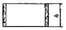
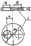
wall rings - in two rows in height in accordance with the diagram shown in the diagram. ;
supporting rings and plates - no more than six rows in height on gaskets (linings) in accordance with the diagram shown in the diagram. .
The scheme of storage of wall rings of wells
Heck. 1
Storage scheme for floor slabs and well bottoms
1 - gaskets (lining); 2 - mounting loops
Heck. 2
Other storage schemes are allowed provided that the structures are kept intact and safety requirements are observed.
ATTACHMENT
Mandatory
SHAPE AND MAIN DIMENSIONS OF WELLS DESIGNS
Table 2
|
Name and form of construction |
Design size |
Sizes, mm |
|||
|
l´ b or a |
|||||
|
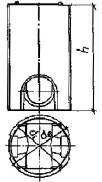
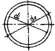
Working chamber of the KDK and KFK types
|
|||||
|
Working chamber of types KLV and KLK
|
|||||
|
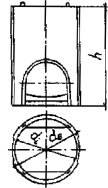
KVG type working chamber |
|||||
|
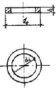
Wall ring of a working chamber or a mouth of a well
|
|||||
|
Support ring
|
|||||
|
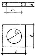
Base plate
|
1700 ´ 1700 |
||||
|
Road plate
|
2500 ´ 1750 |
||||
|
2800 ´ 2000 |
|||||
|
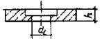
Bottom plate
|
|||||
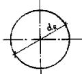
|
Floor slab for water intake wells
|
|||||
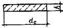
|
Floor slab for sewer, water and gas supply wells
1 - niche (only in plates of standard sizes 3PP20 and 2PP25) |
|||||
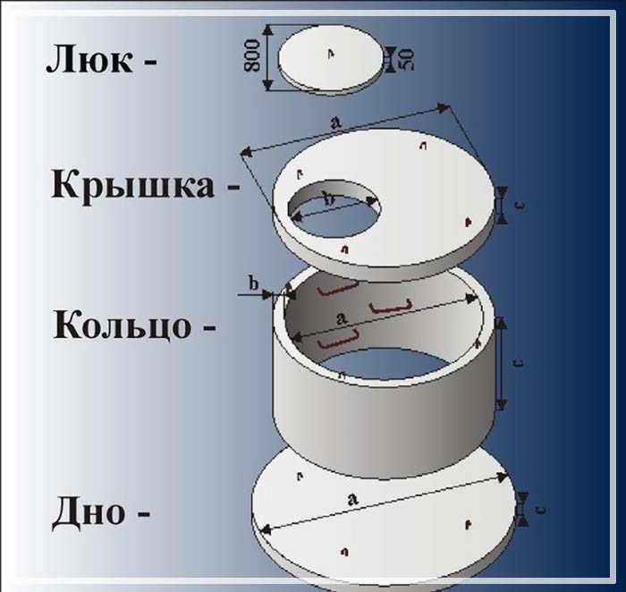
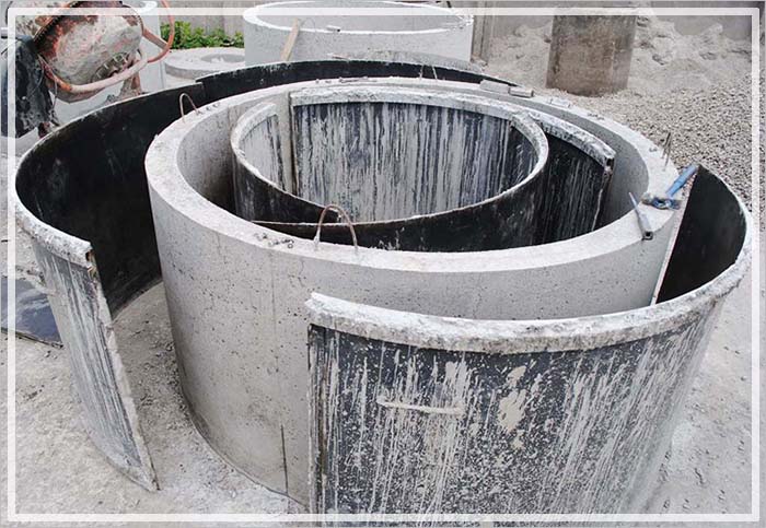
Like any industrial product, reinforced concrete rings for wells should comply with state standards or technical specifications. If they do not comply, the product loses the properties declared by the certificate. Such a ring cannot be installed in a well.
Standard standard
The parameters of reinforced concrete wall rings of the well, including additional (additional name), and the neck rings are regulated by GOST 8020-90 “Concrete and reinforced concrete structures for sewer, water and gas pipelines wells. Technical conditions "edition of 04.2004 with amendments to IMS 3-91. The date of introduction is July 1, 1990. It acts instead of GOST 8020-80.
Regulated ring parameters
This standard applies to all concrete and reinforced concrete rings intended for the construction of round reinforced concrete wells, underground pipelines and various networks. It regulates the following indicators:
- The main parameters and dimensions, marking of the rings (additional relate to the subspecies of the wall);
- Characteristics of materials: concrete, reinforcement, embedded parts, running gear rings;
- Requirements for the appearance of the rings and the quality of the surfaces;
- The values \u200b\u200bof the deviations of the geometric parameters of the rings;
- Completeness of reinforced concrete products;
- Marking rings;
- Reception of concrete products;
- Control methods:
- strength, frost resistance, water tightness, water absorption of concrete;
- welded embedded and reinforcing products;
- ring sizes, sizes of chips and heterogeneities.
- Measurement of concrete products;
- Transportation of rings.
Also shown are storage schemes for rings (wall, additional and neck), bottoms and slabs of wells. In the mandatory application, the forms and basic dimensions of the structures of wall concrete products of the rings (including additional ones) and rings of the neck of the well are established:
- inner diameter;
- outer diameter;
- heights.
Other regulatory documents
| GOST 5781-82 | Hot-rolled steel for reinforcing reinforced concrete structures. |
| GOST 6727-80 * | Cold drawn steel wire for reinforcing reinforced concrete structures. |
| GOST 10060.0-95 | Concrete Methods for determining frost resistance. |
| GOST 10060.1-95 | Concrete The basic method for determining frost resistance. |
| GOST 10060.2-95 | Concrete Accelerated methods for determining frost resistance with multivariate freezing and thawing. |
| GOST 10180-90 | Concrete Methods for determining the strength of control samples. |
| GOST 10884-94 | Reinforcing steel thermomechanically hardened for reinforced concrete structures. |
| GOST 10922-90 | Welded reinforcing and embedded products, welded fittings and embedded products of reinforced concrete structures. General specifications. |
| GOST 12730.0-78 | Concrete General requirements for methods for determining density, humidity, water absorption, porosity and water resistance. |
| GOST 12730.3-78 | Concrete Method for determining water absorption. |
| GOST 12730.5-84 | Concrete Methods for determining water resistance. |
| GOST 13015-2003 | Reinforced concrete and concrete products for construction. General technical requirements. Rules for acceptance, labeling, transportation and storage. |
| GOST 17624-87 | Concrete Ultrasonic method for determining the strength. |
| GOST 17625-83 | Reinforced concrete structures and products. Radiation method for determining the thickness of the protective layer of concrete, dimensions and location of fittings. |
| GOST 18105-86 | Concrete Strength control rules. |
| GOST 22690-88 | Concrete Determination of strength by mechanical methods of non-destructive testing. |
| GOST 22904-93 | Reinforced concrete structures. Magnetic method for determining the thickness of the protective layer of concrete and the location of reinforcement. |
| GOST 23009-78 | Structures and products concrete and reinforced concrete prefabricated. Symbols (marks). |
| GOST 23858-79 | Concrete and reinforced concrete. Methods of testing materials. |
| GOST 26433.0-85 | |
| GOST 26433.1-89 | A system for ensuring the accuracy of geometric parameters in construction. Rules for taking measurements. |
| GOST 26633-91 | Concrete is heavy and fine-grained. Technical conditions |
What does non-compliance with regulatory documents entail?
The Administrative Code of the Russian Federation provides for the administrative liability of manufacturers for non-compliance with the above regulatory documents in the manufacture of reinforced concrete rings. Namely: article 19.19 "Violation of the requirements of technical regulations ...", paragraphs 1-3.
Violation of technical standards in the production of rings leads to a decrease in their quality. So, the use of concrete, different from the regulated GOST 8020-90, will entail a decrease in the strength of the ring, its frost resistance, water resistance. Failure to comply with the technology can lead to air voids inside the ring, chips, bare reinforcement, which will also affect the properties of the ring. Such products must be discarded at the factory.
The use of reinforced concrete rings that do not comply with the applicable standards leads to a reduction in the life of the well and an urgent forced replacement of the rings.
5. EDITION (April 2004) as amended (IMS 3-91)
This standard applies to concrete and reinforced concrete structures made of heavy concrete and intended for the construction of round wells in underground pipelines of sewer, water and gas pipelines.
Designs are used in accordance with the instructions of the working drawings of a particular pipeline.
1. TECHNICAL REQUIREMENTS
1. TECHNICAL REQUIREMENTS
1.1. Designs should be made in accordance with the requirements of this standard and technological documentation approved by the manufacturer according to the working drawings of the series 3.003.1-1 / 87 and 3.900.1-14.
(Amendment)
1.2. Key parameters and dimensions
1.2.1. Designs are divided into types:
KFK - a working chamber of a well of household (fecal) sewage;
KDK - the same as intra-quarter networks;
KLK - the same storm storm;
KLV - the same, storm sewer, water intake;
KVG - the same, water and gas networks;
KS - wall ring of the working chamber or the neck of the well;
KO - support ring;
PO - base plate;
PD - road plate;
PN - bottom plate;
PP - floor slab.
1.2.2. The shape and main dimensions of the structures of the wells must comply with those indicated in the appendix.
In cases provided for by the working drawings of a particular pipeline, structures may have embedded products, as well as niche openings and cutouts that differ in location and size from those adopted in the working drawings of series 3.003.1-1 / 87 and 3.900.1-14.
(Amendment)
1.2.3. The consumption rates of concrete and steel on the structure of the wells must comply with those specified in the working drawings for these structures.
1.2.4. Floor slabs are divided into groups according to bearing capacity, depending on the depth of the slabs and the load on the surface of the soil backfill according to the instructions of the working drawings.
1.2.5. Designs are marked with marks in accordance with the requirements GOST 23009 . A design brand consists of alphanumeric groups separated by hyphens.
In the first group, the design size is given. The letters indicate the type of construction, the numbers before the letters indicate the serial number of the size (if necessary), the numbers after the letters (rounded to the nearest whole number) indicate (in decimeters):
For working chambers and support rings - their inner diameter;
For bottom plates and ceilings - the inner diameter of the wells;
For wall rings, their inner diameter and height;
For base and road slabs - hole diameter.
In the second group for floor slabs indicate the group by bearing capacity.
In the third group for floor slabs or in the second group for other structures, indicate:
For structures operated under aggressive environmental conditions, - the permeability index of concrete, indicated by a capital letter: H - normal permeability, P - low permeability, O - particularly low permeability;
Additional design characteristics (the presence of embedded products, holes, niches and cutouts) indicated in the mark in Arabic numerals or letters.
An example of a symbol (brand) of a working chamber of the KFK type with an internal diameter of 1250 mm:
KFK13
The same, wall ring with an inner diameter of 2500 mm, a height of 1190 mm:
KC25.12
The same, floor slabs, overlapping the well, with an inner diameter of 2000 mm, with a hole with a diameter of 1000 mm (size 2PP20), the second group in bearing capacity:
2PP20-2
Note. It is allowed to accept designations of brands of structures in accordance with the working drawings for these structures until they are reviewed.
1.3. Specifications
1.3.1. Designs must meet the requirements GOST 13015 *:
________________
GOST 13015-2012 , hereinafter
- by strength, rigidity and crack resistance; at the same time, there are no requirements for testing structures by loading;
According to the actual concrete strength indicators (at the design age and holiday);
On frost resistance and water tightness of concrete;
By the thickness of the protective layer of concrete to reinforcement;
To steel grades for reinforcing and embedded products, including for mounting loops;
Corrosion protection.
1.3.2. Structures should be made of heavy concrete according to GOST 26633 * classes or brands of compressive strength specified in the design drawings of structures.
________________
* The document is not valid in the territory of the Russian Federation. Is acting GOST 26633-2012 - Note by the manufacturer of the database.
1.3.3. The normalized tempering strength of concrete is taken equal to 70% of the class or grade of concrete in terms of compressive strength.
The specified normalized tempering strength of concrete can be reduced or increased in accordance with the requirements GOST 13015.
1.3.4. The water absorption of concrete structures must comply with the established design documentation for a particular structure or specified when ordering structures.
1.3.5. For reinforcing structures, reinforcing steel of the following types and classes is used:
Thermomechanically hardened core classes of At-IIIC and At-IVC classes GOST 10884 *;
________________
* The document is not valid in the territory of the Russian Federation. Is acting GOST 10884-94 . - Note by the manufacturer of the database.
Hot-rolled rod classes A-I, A-II and A-III in GOST 5781 ;
Reinforcing wire of class BP-I GOST 6727.
1.3.6. The shape and dimensions of reinforcing and embedded products and their position in the structures must correspond to those indicated in the working drawings.
1.3.7. Welded reinforcing and embedded products must meet the requirements GOST 10922 *.
________________
* The document is not valid in the territory of the Russian Federation. Is acting GOST 10922-2012
1.3.8. In the cases provided for by the working drawings of wells, running brackets should be installed inside the wall rings, located along the height of the ring after 300 mm and protruding 120 mm from the inner surface of the rings.
Running braces should be made of reinforcing steel of classes A-I and A-II according to GOST 5781.
By agreement between the manufacturer and the consumer, wall rings are allowed to be made without running brackets, provided that they are installed at the construction site.
1.3.9. Running brackets must be protected against corrosion according to the instructions of the working drawings of the wells.
1.3.10. Values \u200b\u200bof actual deviations of the geometric parameters of the structures should not exceed the limit values \u200b\u200bindicated in Table 1.
Table 1
In millimeters
The name of the deviation of the geometric parameter | The name of the geometric parameter | Prev off |
Deviation from the linear size | Height (thickness) of the structure: | |
st. 1000 to 1600 | ||
The inner diameter of the working chambers, wall and support rings, the outer diameter of the floor slabs and the bottom, the diameter of the manholes and openings for pipelines: | ||
st. 1000 to 1600 | ||
Length and width of base and road slabs | ||
Position of holes and cutouts | ||
Deviation from flatness of the bottom surface of floor slabs (when measured from a conventional plane passing through three points) | Outer diameter of floor slabs: | |
st. 1000 to 2500 | ||
1.3.11. Requirements for the quality of surfaces and the appearance of structures - according GOST 13015 . At the same time, the quality of the surfaces of structures (except for butt surfaces) must satisfy the requirements established for category A6. The surfaces forming the joint of structures that are monolithic at the construction site are subject to the requirements established for category A7.
By agreement of the manufacturer with the consumer, it is allowed to submit to all surfaces of the working chambers, wall and support rings the requirements established for category A7.
1.4. Completeness
1.4.1. Working chambers are supplied to the consumer complete with floor slabs.
1.5. Marking
1.5.1. Design marking - by GOST 13015 . Marking is applied to the outer side surface of structures.
2. ACCEPTANCE
2.1. Acceptance of structures - by GOST 13015 and this standard. In this design accept:
According to the results of periodic tests - in terms of frost resistance, water tightness and water absorption of concrete;
According to the results of acceptance tests - according to indicators of concrete strength (class or grade for compressive strength and tempering strength), compliance of reinforcing and embedded products to working drawings, strength of welded joints, concrete protective layer thickness to reinforcement, accuracy of geometric parameters, quality of concrete surface.
Acceptance of structures for strength, rigidity and crack resistance is carried out according to a set of standardized and design indicators in accordance with the requirements GOST 13015.
2.2. Acceptance of structures according to the accuracy of geometric parameters, the thickness of the protective layer of concrete to reinforcement, surface quality is carried out according to the results of selective control.
2.3. In the document on the quality of designs for GOST 13015 in addition, concrete grades on frost resistance and water resistance of concrete should be given (if these indicators are specified in the order for the manufacture of structures).
3. CONTROL METHODS
3.1. The strength of concrete structures is determined by GOST 10180 * on a series of samples made from concrete mix of the working composition and stored in the conditions established GOST 18105 **.
________________
* The document is not valid in the territory of the Russian Federation. Is acting GOST 10180-2012 ;
** The document is not valid in the territory of the Russian Federation. Is acting GOST 18105-2010 . - Note by the manufacturer of the database.
When tested with non-destructive methods, the actual compressive strength of concrete should be determined using the ultrasonic method GOST 17624 * or devices of mechanical action according to GOST 22690 , as well as other methods provided by the standards for concrete testing methods.
________________
* The document is not valid in the territory of the Russian Federation. Is acting GOST 17624-2012 . - Note by the manufacturer of the database.
3.2. The frost resistance of concrete is determined by GOST 10060.0 -GOST 10060.2 * on a series of samples made of concrete mixture of the working composition.
________________
* The document is not valid in the territory of the Russian Federation. Is acting GOST 10060-2012 . - Note by the manufacturer of the database.
3.3. The water resistance of concrete is determined by GOST 12730.0 and GOST 12730.5.
3.4. Water absorption of concrete is determined by GOST 12730.0 and GOST 12730.3.
3.5. Welded reinforcing and embedded products are controlled by GOST 10922 and GOST 23858.
3.6. The dimensions and position of reinforcing and embedded products, as well as the thickness of the protective layer of concrete to reinforcement, are determined by GOST 17625 or GOST 22904.
3.7. Dimensions, deviations from the flatness of structures, the width of the surface technological cracks, the dimensions of shells, sag and chips of concrete structures are checked by methods established GOST 26433.0 and GOST 26433.1.
3.8. Dimensions of structures are checked as follows:
The outer and inner diameters of the working chambers, wall and support rings, floor slabs and bottoms are measured by two mutually perpendicular diameters;
The wall thickness of the working chambers and wall rings is measured in four places at two mutually perpendicular diameters;
The height of the working chambers and wall rings is measured by four generators in two diametrically opposite sections;
The thickness of the plates and the support ring is measured in four places in two mutually perpendicular directions.
4. TRANSPORTATION AND STORAGE
4.1. Transportation and storage of structures - by GOST 13015 and this standard.
4.2. Designs are transported and stored in working position.
4.3. Structures should be stored:
Working chambers - in one row;
Wall rings - in two rows in height in accordance with the diagram shown in Fig. 1;
- supporting rings and plates - not more than six rows in height on gaskets (linings) in accordance with the diagram shown in Fig. 2.
Damn. 1. The scheme of storage of wall rings of wells
The scheme of storage of wall rings of wells
Damn. 1
Damn. 2. Storage scheme for floor slabs and well bottoms
Storage scheme for floor slabs and well bottoms
1 - gaskets (lining); 2 - mounting loops.
Other storage schemes are allowed provided that the structures are kept intact and safety requirements are observed.
ANNEX (mandatory). SHAPE AND BASIC DIMENSIONS OF WELLS DESIGNS
ATTACHMENT
Mandatory
table 2
Name and form | Design size | Sizes, mm |
|||
Working chamber of the KDK and KFK types | |||||
Working chamber of types KLV and KLK | |||||
KVG type working chamber | |||||
Wall ring of a working chamber or a mouth of a well | |||||
Support ring | |||||
Base plate | |||||
Road plate | |||||
Bottom plate | |||||
Floor slab for water intake wells | |||||
Floor slab for sewer, water and gas pipelines | |||||
1 - niche (only in plates of standard sizes 3PP20 and 2PP25) | |||||
Notes: 1. The inner surfaces of the working chambers and wall rings may have a technological slope of not more than 1.5%. In this case, the inner diameter and wall thickness in the middle of the height of the structure must correspond to those indicated in the working drawings of the structures.
2. The side faces of plates manufactured in one-piece forms may have a technological slope of not more than 10%.
3. It is allowed to increase the height of the wall rings by a factor of 300 mm to a height of 1790 mm.
4. It is allowed to manufacture slabs of standard sizes 1PP20 and 2PPP with a thickness of 150 mm on existing equipment on 01/01/93.
Electronic text of the document
prepared by Codex JSC and verified against:
official publication
M .: IPK Standards Publishing House, 2004