Forms of impellers of centrifugal pumps. The device and principle of operation of centrifugal pumps. Types of impellers of centrifugal pumps
BASIC EQUATION
CENTRIFUGAL PUMP
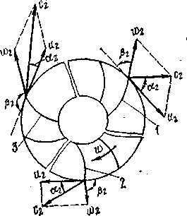
The fluid in the impeller of the centrifugal pump makes a complex movement.
W is the speed of relative motion along the blade due to centrifugal forces
u - peripheral speed
c is the absolute velocity of the fluid
u \u003d ωR \u003d 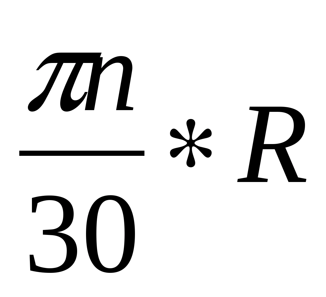
The advantage of vertical pumps is that they require a very small horizontal space, which makes them indispensable on ships, wells, etc .; however, sufficient vertical space is required to ensure easy assembly and disassembly.
For high-pressure pumps, a vertical design is generally less expensive than a horizontal one. Vertical pumps are commonly used in marine applications, for dirty water, drainage, irrigation, condenser circulation, etc. If this depth is less or less than the diameter of the suction port, vortices or vortices can be created on the surface of the center from which air is supplied to the pump, resulting in loss of flow and poor functioning.
The theoretical pressure is determined by the formula:
N n t \u003d 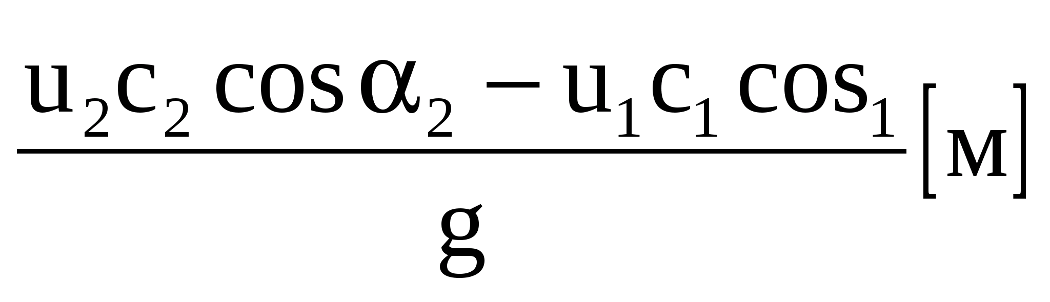 - equation of L. Euler (1754)
Based on the conditions of shock-free fluid entry into the wheel in order to avoid large pressure losses, the liquid is usually fed into the wheel in a radial direction, i.e.  1 =90 0
.
1 =90 0
.
Types of impellers of centrifugal pumps
The shaft from which these pumps are installed is usually driven by separate plain bearings at regular intervals and is lubricated with oil, grease or the same pumped liquid; in the latter case, the shaft is usually located inside the vertical drive pipe, next to the engine, where it is horizontally deflected by a suitable elbow.
In cases of lubrication or oil lubrication, the shaft enters into the bearing tube of the bearings, and this assembly, in turn, is external or internal to the supply tube. Another solution has the advantage of requiring less space, in both cases packaging is unnecessary, which is also a very favorable circumstance, given the disadvantages that this sometimes leads to.
1 \u003d 90 0, cos90 0 \u003d 0
N n t \u003d 8 ÷ 15
The actual pressure is less than theoretical for the following reasons:
part of the pressure is spent on overcoming the hydraulic resistance inside the pump;
not all fluid particles taken along the width of the channel between two adjacent vanes move with the same speeds; therefore, the speed triangles at the wheel inlet are not the same for different trickles.
Submersible pumps have the advantage of occupying the minimum horizontal space only necessary to accommodate a vertical motor and drive, even sometimes it is underground. The hydraulic advantages are obvious when all suction problems disappear, which are the main disadvantage in the operation of centrifugal pumps.
Types of impellers
From a mechanical point of view, this arrangement represents the main disadvantages relative to the horizontal. Pumps are initially more expensive, and their maintenance is much higher, since any repair requires dismantling the pump to raise it to the surface.
Losses of pressure to overcome hydraulic resistance are taken into account by hydraulic efficiency
η t \u003d 0.8 ÷ 0.95
The pressure drop for the second reason is taken into account by the coefficient κ.
N n d \u003d 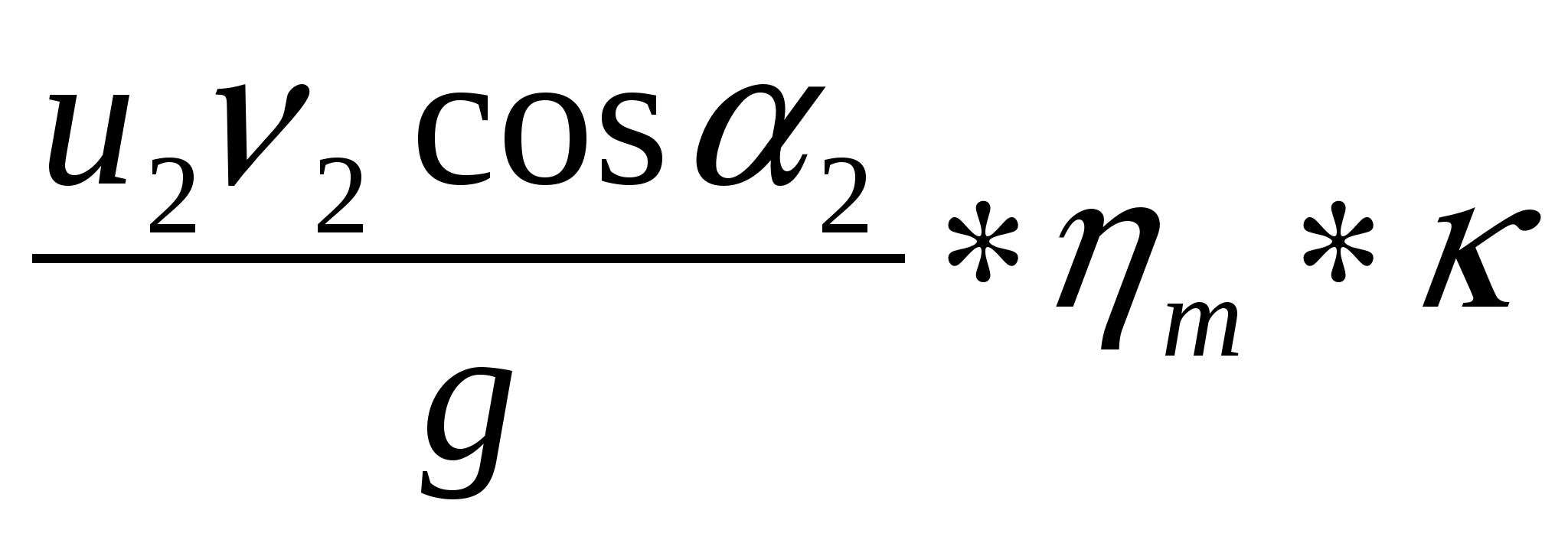
INFLUENCE OF SHAPE FORM ON DEVELOPED HEAD
The remaining components of centrifugal pumps
An elongated shaft, subjecting the bearings to hard work, especially if they are lubricated with water or fluids without great lubricating properties, makes their life short and unpredictable. The most important types of vertical submersible pumps are vertical or deep borehole turbine pumps, screw pumps, and submersible scroll pumps.
Among the submersible pumps, the most important are deep well, sounding, or vertical turbines that have been developed for well, boring, and small-diameter drilling. This circumstance necessarily limits the height for each stage, which leads to the concept of multicellular pumps to reduce space.
In a centrifugal pump, three types of blades can be used in curvature relative to the direction of rotation of the wheel:
1. bent back;
2. bent radially;
3. bent forward
R 1, R 2, n \u003d const
u 2 \u003d 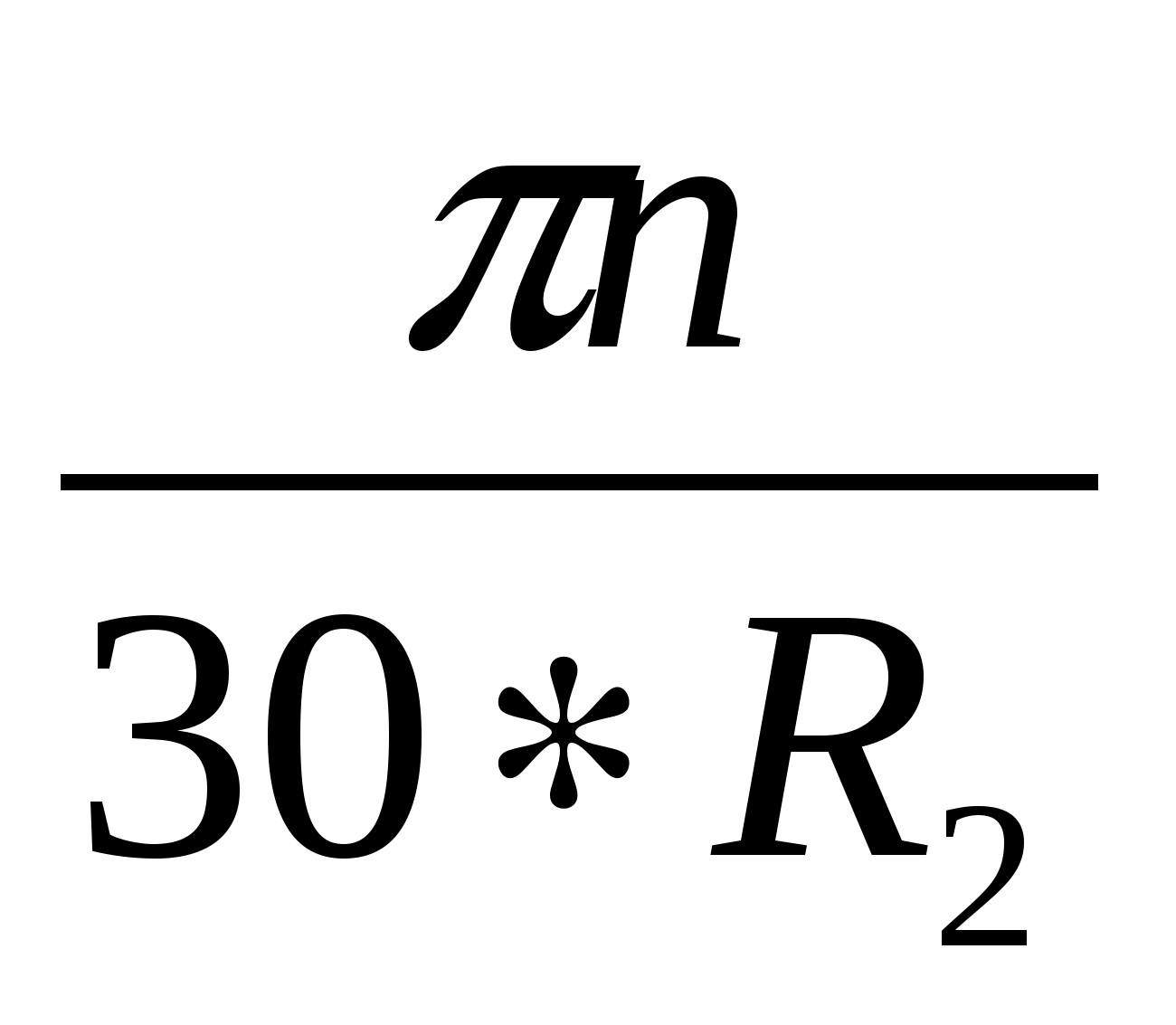
At the same speed and size of the wheels, the forward-curved blades give the greatest absolute speed, therefore, the greatest theoretical pressure is given by the forward-curved blades. However, if the fluid velocity at the pump outlet is large, then the hydraulic losses increase in proportion to the square of the velocity. Therefore, wheels with forward-curved blades have a lower efficiency than with backward-curved blades.
A simple suction impeller can be radial or diagonal, depending on the operating conditions and its closed or half-open design. However, half-open impellers, in addition to their greater axial thrust, up to 50% more, require more careful vertical adjustment during assembly.
The diffuser assembly of the pump housing and the supply pipe hang from the head on which the motor is mounted, making up the elbow of the drive deflection. Sometimes the diffusers are coated with internal enamel, which reduces the roughness of the casting and subsequent hydraulic losses, increasing the yield, providing a certain uniformity for different nodes, providing better resistance to corrosion and abrasion.
In addition, the channels between the shoulder blades bent back expand more smoothly than when the shoulder blades bent forward. Therefore, for pumps always use wheels with backward curved blades, because they provide the greatest efficiency pump.
PUMP PRESSURE DETERMINED BY INDICATIONS OF INSTRUMENTS
The pump in relation to the liquid level can be installed in two ways:
Centrifugal Pump: A General View
The design of these pumps allows you to set the desired number of stages, which can reach 20 or more, simply adding diffusers and similar impellers on top of each other, which gives a certain elasticity for applications with the resulting benefits of standardization, the availability of spare parts, etc .; however, these pumps share the drawbacks mentioned above for vertical submersible pumps in order to be expensive and require high maintenance costs.
Vertical turbine pumps have achieved remarkable excellence with high outputs and some hydraulic advantages; although they began to be used exclusively for irrigation in wells and drilling, their industrial applications are growing more and more than agriculture, the reason why the name of deep-well pumps disappears in order to adapt to one of the vertical turbine pumps. Inside this type, pumps with an elongated shaft and driven by a submersible motor located directly below the pump or divers' pumps can be distinguished.
the pump is located above the reservoir fluid level
M
The pump head is determined by the formula:
H n \u003d 10Rm + 10Rv + 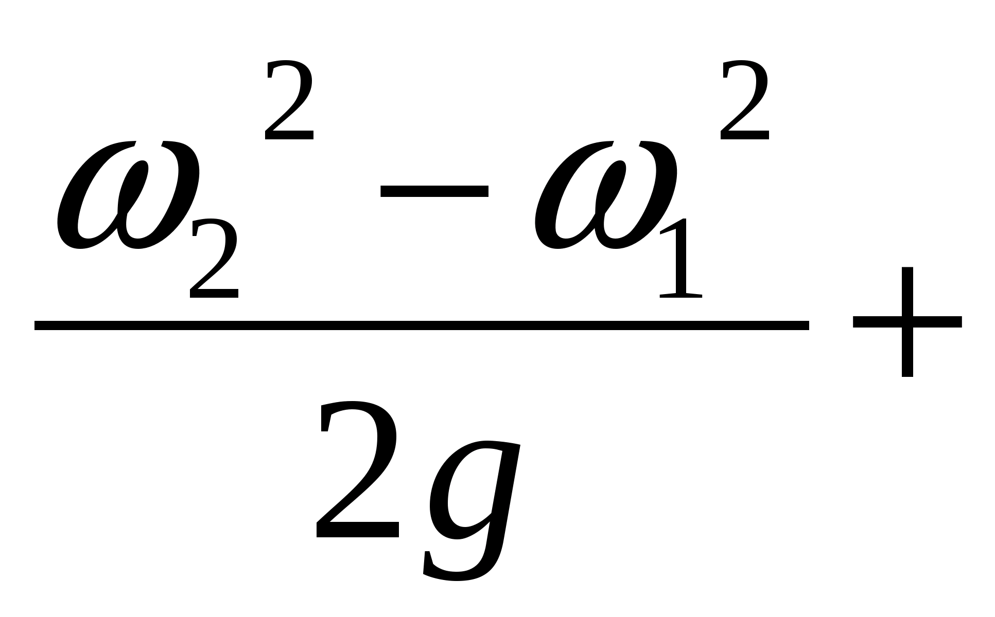 z M.V. [m]
where: R m, R in the testimony of a manometer and a vacuum gauge in kgf / cm 2;
ω 2, ω 1 - fluid velocity at the outlet and inlet of the pump;
Z m. - the distance between the marks of the manometer and the gauge.
In case of any malfunction, the pump stops, inspection and troubleshooting
In these pumps, the shaft passes through the inside of the supply pipe, bare if it is lubricated with oil or inside the protective tube if it is lubricated with water from an external source. A set of impellers and a shaft supported by thrust bearings are located in the same head or in the upper part of the engine if its axis and one of the pumps are rigidly connected.
These pumps can reach 200 m.s. but the problems caused by any imperfection in the straightness of the shaft, which significantly affects the service life of bearings and vibration, increase significantly with the length of the shaft. To avoid the disadvantages caused by the excessive length of the shaft, submersible pumps have developed motors that are able to work, in turn, are surrounded by fluid and are sized so that they can be installed inside the well.
2 The pump is located “under the bay”, i.e. suction overpressure
N n \u003d 10Rm 2 - 10Rm 1 + 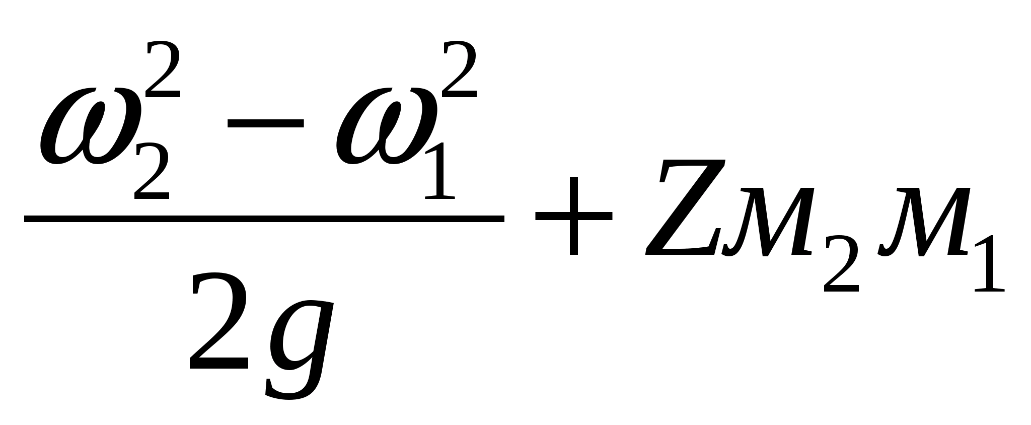
Z m.2m1 - the distance between the marks of the pressure gauges;
P m1, P m2 - readings of pressure gauges.
LAW OF PROPORTIONALITY
The ratio describing the dependence of the flow rate and power on the speed is called the law of proportionality.
Thus, by placing the motors directly below the pump, the need for a shaft, bearings and protective tube disappears, so that the column can have a smaller diameter for similar load losses. Engines can be dry operated with sealed or flooded, in which case the insulation must have very special characteristics. The advantages of the underwater engine are becoming noticeable, especially in deep wells over 30 m, or inclined or curved. The required surface space is obviously minimal and even empty with an underground discharge.
n 1 - ν 1, W 1, u 1
n 2 - ν 2, W 2, u 2
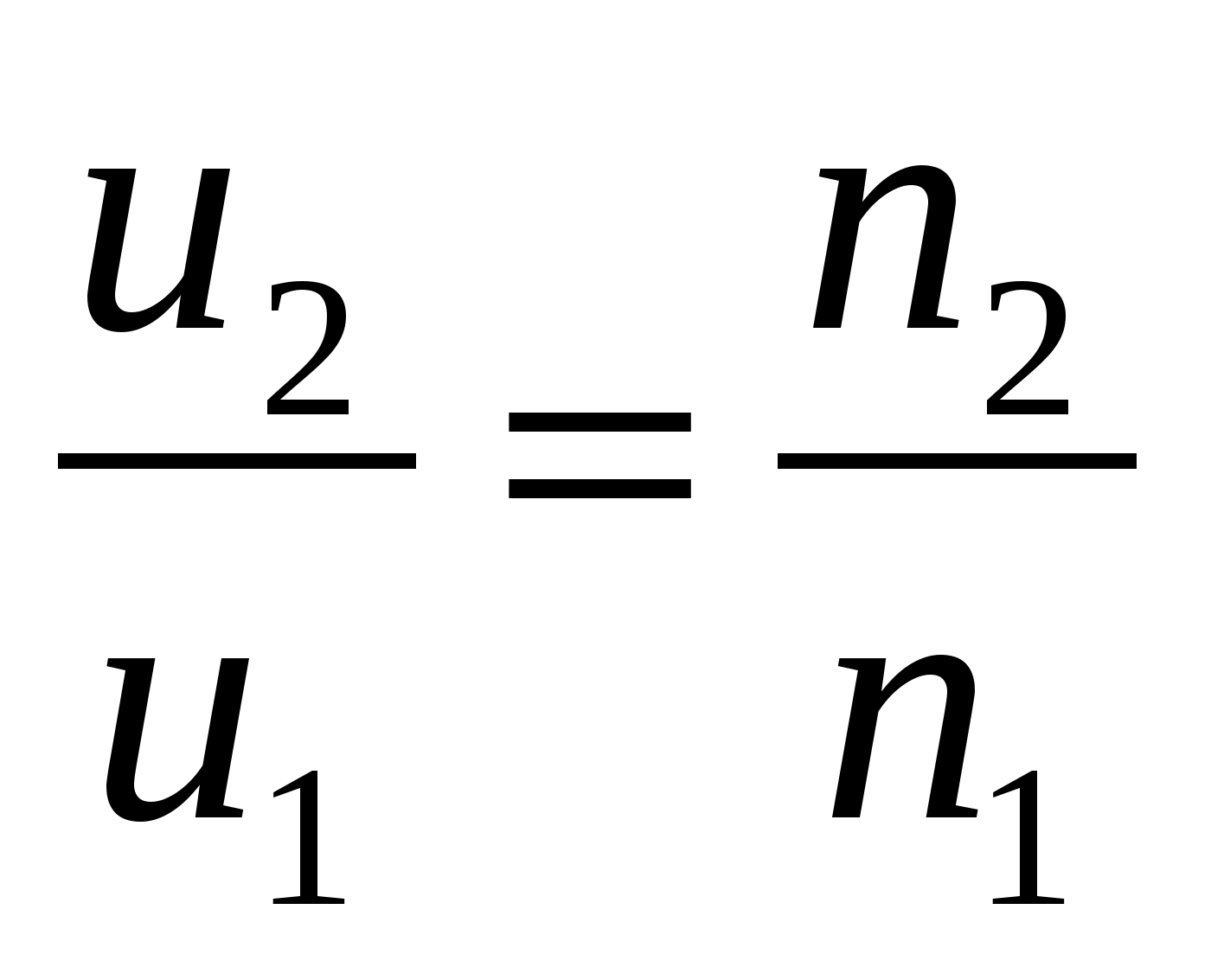
The pump flow is proportional to the radial component of the output velocity.
Volumetric efficiency (η 0) remains almost unchanged when the speed changes within 50%.
From this formula it can be seen that u 2, ν 2 each of which depends on the number of revolutions
The disadvantages are lower performance and lower engine life and the inevitable need for complete disassembly for any repair or repair of the pump or engine. To control large flows with small heights, propeller pumps are often used in vertical and submerged modes. The simplicity of these pumps sometimes becomes maximum, consisting only of an open axial impeller, equipped with a vertical shaft that rotates inside the column or drive pipe.
Sometimes they may carry a diffuser or some guide blades; Directional vanes can also be provided on one of these pumps to prevent or reduce excessive preliminary rotation of the fluid vein in the suction, which can lead to the formation of vortices or vortices on the surface of the liquid.
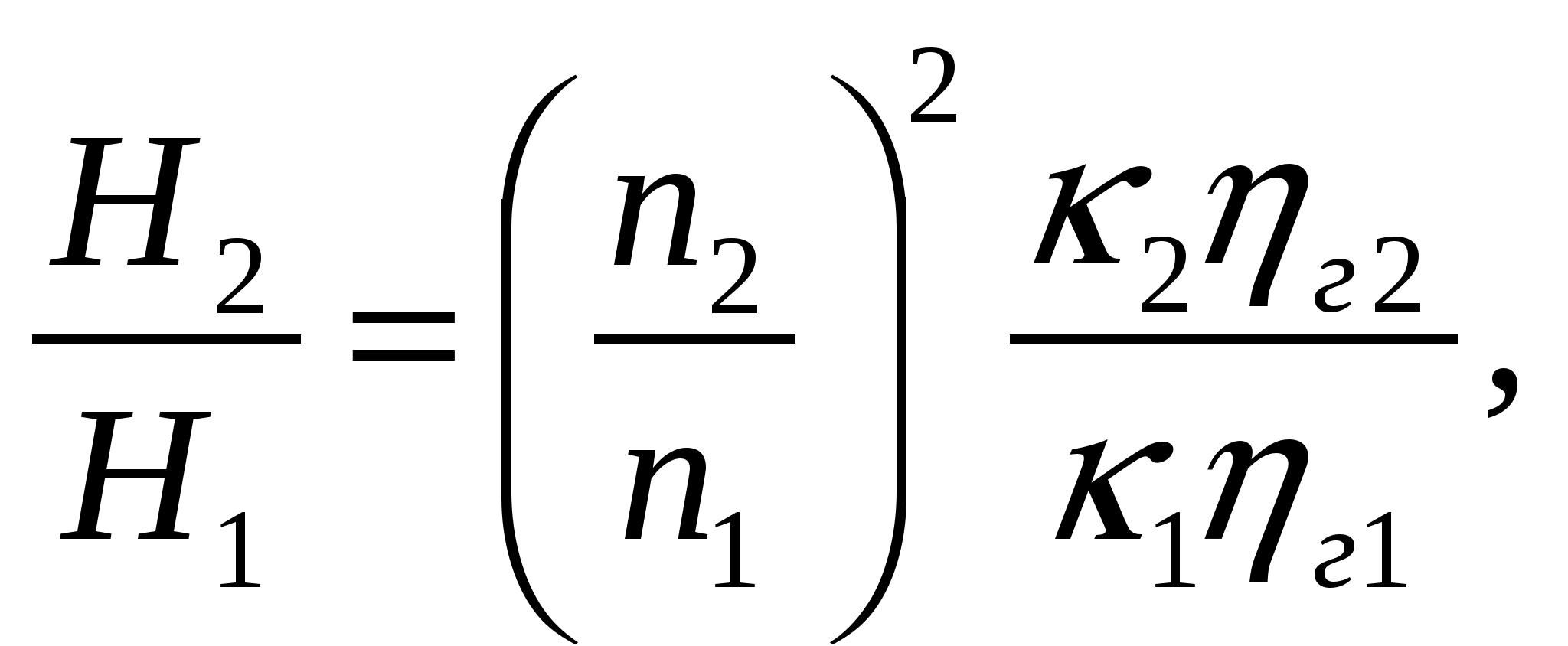 where κ 2 and η g with a change in the number of revolutions within 50% remain unchanged, therefore, the formula takes the form:
LAW OF SIMILARITY
When designing and operating centrifugal pumps, they use the laws of their similarity and, first of all, the similarity of the impellers of these pumps. Distinguish geometric and kinematic similarity of impellers.
The shaft can be lubricated with oil, in which case it is located inside the corresponding protective tube with bearings. The impeller can be cantilevered or have a lower bearing, which, although it is a small obstacle to suction, plays an important role, given the narrow radial dose between the impeller and the surrounding pipe.
In some pumps of this type, the shaft and impeller can be dismantled from above without removing the column, which facilitates accessibility and maintenance, which is perhaps the most serious drawback of submersible pumps. We considered all centrifugal or centrifugal pumps as centrifugal pumps, in which energy is transferred to the liquid essentially under the action of centrifugal force until axial, in which energy will not enter the liquid by the momentum exerted by the blade on it.
Geometric similarity means the proportionality of the corresponding dimensions of their flow part (d, the width of the blades, the radii of curvature of the blades, etc.)
Kinematic similarity predetermines the same direction of the velocity vectors at similar points in the flow.
If the geometric similarity of the wheels d 2 and d 1 rotate with the same speed, then the following dependencies are obtained.
In radial centrifugal pumps, fluid flow is checked in radial planes, axial planes on cylindrical surfaces around the axis of rotation and in diagonals are checked radially and in the axial direction, also called mixed flow. The type of pump, according to this first classification, which relates to the hydraulic design of the impeller, is indicated by its specific speed at the point of maximum output of the characteristic curve.
Each impeller has a specific specific speed, although this also depends on the diffuser system. Geometrically similar, although they may have slight deviations from the exit angle, blade shape, etc. Specific speed-performance. Leaks are also great.
The feed is proportional to the area of \u200b\u200bthe output section of the impeller and the radial component of the output velocity. If the impellers are similar, then the output cross-sectional area is proportional to d 2, and the output speed is proportional to d, therefore:
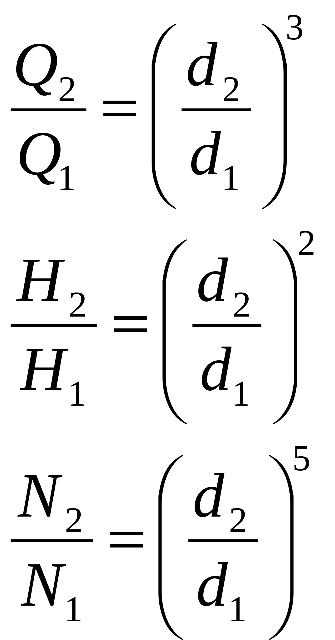
Speed \u200b\u200bfactor - the number of revolutions per minute of the impeller, which is geometrically similar to the impeller under consideration and when the fluid is supplied Q \u003d 75 l / s provides a pressure of H \u003d 1 m.
The axial shift indicator is removed
As the specific velocity increases, productivity improves to a certain value, above which higher diffusion losses and insufficient fluid direction cause it to decrease again, albeit more gently. The fact that pumps with the same specific speed can have different yields that are lower for lower flow rates is explained by the fact that the laws of hydraulic similarity are not quite exactly implemented taking into account the existing geometric similarity.
Shaft Recovery Technology
Currently, the curves are moving gradually upward, as the technique is becoming more and more complex pumps. Given its mechanical or structural design, three types of impellers can be distinguished. This classification does not depend on the most general, which is related to the type of hydraulic design, so in this new classification there can be centrifugal and mixed flows, open, semi-open or closed impellers.
n s \u003d 3.65 
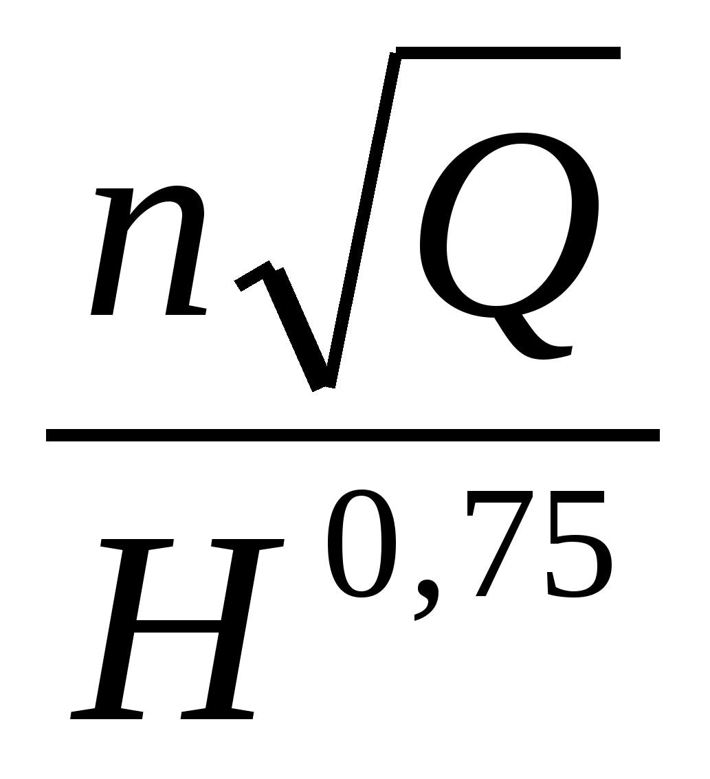 where n is the number of revolutions in 1 min.
Q [m 3 / s]
Note: for pumps with two-way fluid supply to the impeller, Q / 2 is substituted in the formula.
n s \u003d 50 - 80 low-speed pumps;
n s \u003d 80 - 150 normal speed pumps;
Closed two-story semi-open outdoor. Axial impellers in their structure can only be half open or closed, since their blades can be considered as being supported laterally on the axis of rotation, which serves as the hub of the impeller, as if it were a rear wall with radial and diagonals.
Open impellers. In an open impeller, bare blades are attached only to the pivot axis and move between two fixed side walls belonging to the pump casing with narrow lateral tolerances to avoid leakage. In practice, no distinction is made between open and semi-open impellers, meaning both open and closed. Open impellers are used in some small radial pumps and for pumping abrasive fluids.
n s \u003d 150 - 300 high-speed pumps.
With an increase in speed, the ratio of the diameter of the impeller to the diameter of the entrance to the impeller decreases from 3-2.5 (low-speed) to 1.8 - 1.4 (high-speed).
n s ↓ - Q ↓ H
AXIAL EFFORT AND WAYS TO REDUCE IT
Occurrence pattern
Axial pressure:
2-impeller;
3 and 4-gaps between
![]() P1 D2 impeller
P1 D2 impeller
And pump housing.
On the impeller of a centrifugal pump with a one-way fluid inlet
there is an axial force directed towards the entrance. It arises due to the unevenness of the pressure forces acting on the right and left on the impeller.
In the cavity between the housing and the impeller filled with the pumped liquid, the pressure is equal to the pressure at the outlet of the impeller.
Pressure force directed to the right:
F 1 \u003d p 1 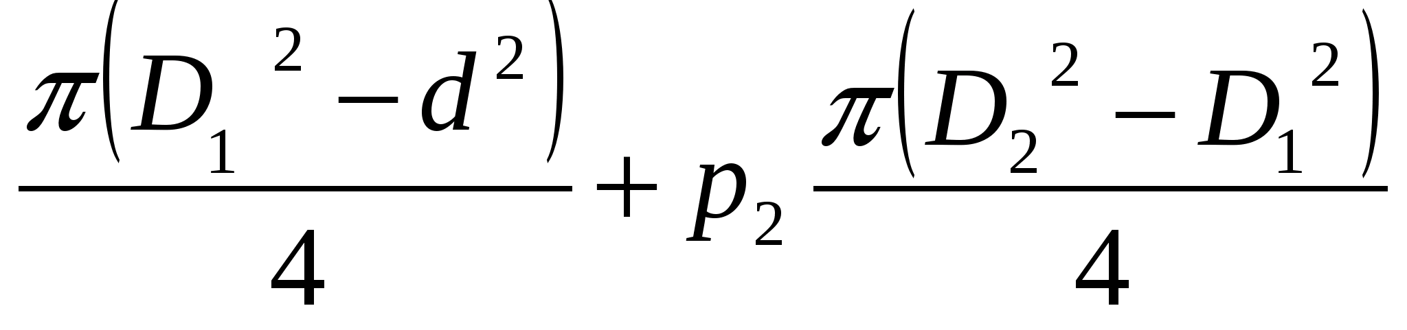
Pressure force is directed to the left:
F 2 \u003d p 2 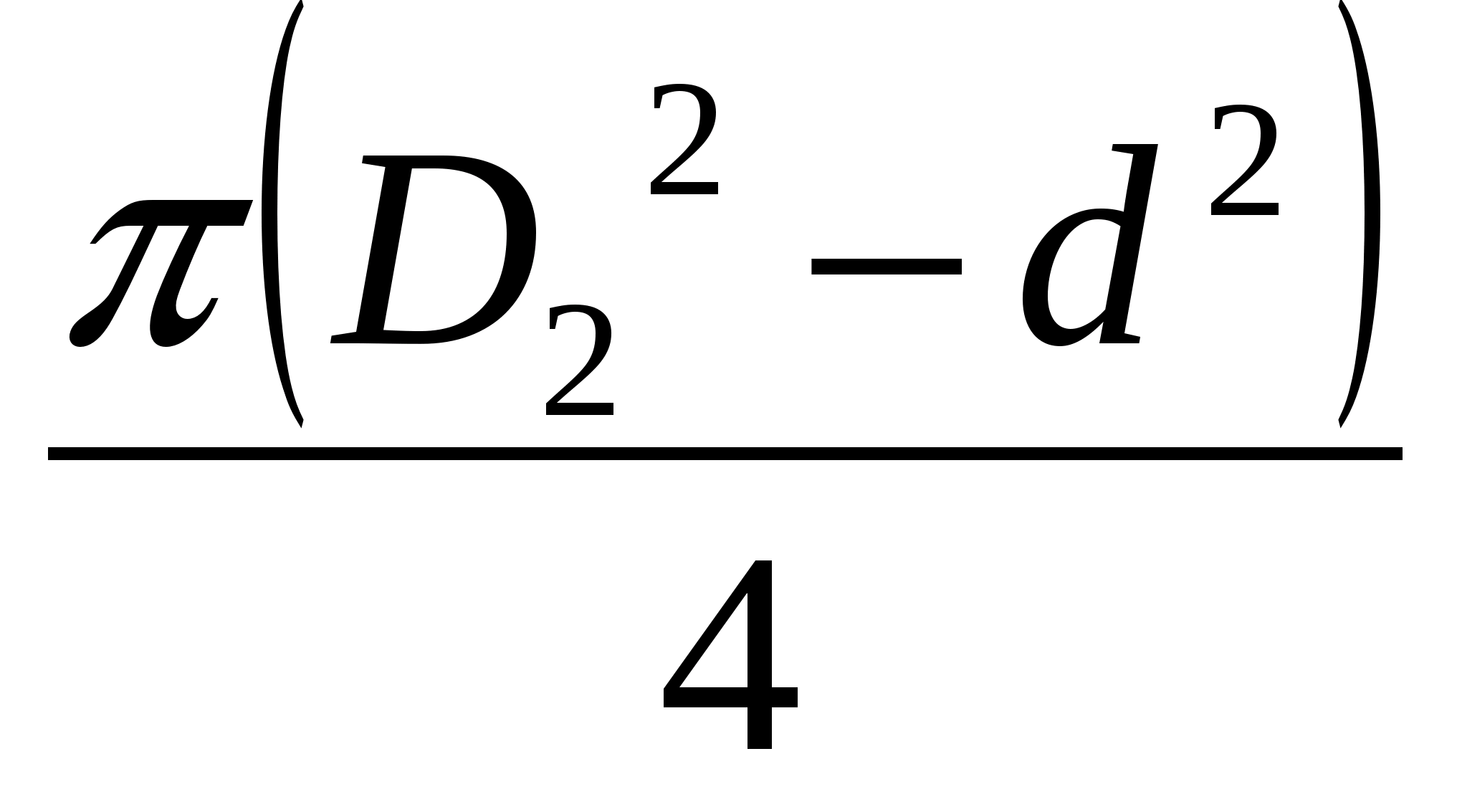
F \u003d F 2 -F 1 \u003d (p 2 -p 1) 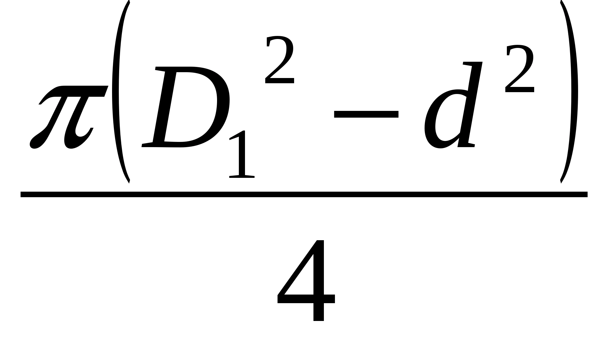
Axial pressure can be balanced in several ways.
the use of 2 x third-party wheels, which due to symmetry does not cause axial force; to fix the shaft in the axial direction and the perception of random axial forces apply angular contact bearings;
installation of additional sealing rings and drilling of the unloading holes of the hub, due to which the pressure acting on both sides of the impeller is almost completely equalized;
installation of a hydraulic heel in multistage pumps of section type.
CAVITATION
PUMP STOP HEIGHT
Typically, when the pump is operating, increased pressure is created on its suction side. If this is a vacuum such that the pressure at the inlet edges of the impellers is lower than the vapor pressure of the pumped liquid at a given temperature, then vaporization of the liquid occurs in the cavity of the impeller. The phenomenon that occurs in this case (erosion, corrosion, vibration, noise, pressure drop) is called cavitation.
Therefore, it is necessary that the suction pressure be greater than the vapor pressure of the liquid at a given temperature.
The cavitation phenomenon has a strong effect on cast iron and carbon steel. The most stable in this regard are stainless steel and bronze. Recently, to protect against the phenomenon of cavitation, the most susceptible cavitation parts are coated with protective hard alloys.
To prevent the phenomenon of cavitation, the correct installation height of the pump is necessary, which can be determined from the following formula:
N vac. \u003d N m.v. + N bp + 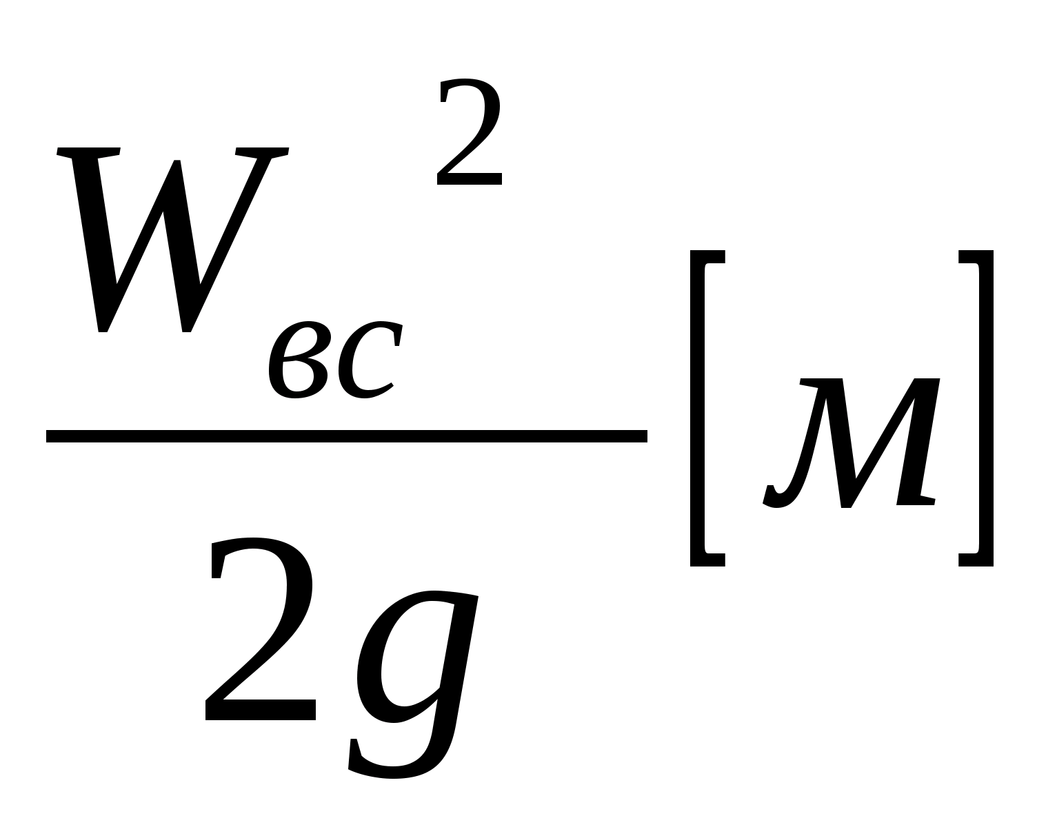
For each pump, the characteristic indicates the line H vac. add. , therefore, N vac. N vac. add. .
CENTRIFUGAL PUMP CHARACTERISTIC
The graphical dependence of the main technical indicators (pressure, power, efficiency, Δh add.) On the feed at constant values \u200b\u200bof the impeller speed, viscosity and density of the liquid is called pump characteristic .
Distinguish between theoretical and experimental (real, working) characteristics of the pumps.
Theoretical characteristics are obtained using the basic equations of a centrifugal pump, which introduce corrections to the actual operating conditions of the pump unit. Since the operation of the pump is affected by a large number of factors that are difficult and sometimes impossible to take into account, the theoretical characteristics of the pumps are inaccurate and are practically not used.
The true relationship between the parameters of the centrifugal pump is determined experimentally as a result of factory (bench) tests of the pump or its model.
After starting the pump, the flow rate is controlled by changing the degree of opening of the valve on the pressure line. Thus, several supply values \u200b\u200bare set and the values \u200b\u200bof pressure and power consumption corresponding to these values \u200b\u200bare measured.
According to the data obtained as a result of the experiments, graphs are constructed - characteristics of the pumps.
2 - characteristic of the pipeline with a closed valve;
3 - pump characteristic.
The actual fluid supply is determined by the intersection of the characteristics of the pipeline and the characteristics of the pump.
PARALLEL AND SEQUENTIAL
PUMP WORK
At thermal power plants, there is often a joint operation of two or more working pumps, while the pumps can turn on both in parallel and in series. Two or more pumps are switched on at thermal stations in parallel in cases where one pump does not provide the necessary supply. To increase the pressure, the pumps are switched on in series. To analyze the joint operation of the pumps, their total characteristic is built.
The operation of centrifugal pumps with parallel (a) and series (b) connection:
1 - characteristic of the first pump;
2 - characteristic of the second pump;
3 - characteristic of the pipeline; 4-sum characteristic of two pumps
When constructing the total characteristics of the pumps, it is necessary to remember the following:
when the pumps are switched on in parallel, the flows are added at equal pressures; when connected in series, the pressures are added at equal flows.
Parallel operation of the pumps is advisable with a gentle characteristic of the pipeline, i.e. least resistance. For this purpose, when designing, slightly larger diameters of the pipelines are adopted.
Sequential operation of the pumps is advisable with a steep characteristic of the pipeline, i.e. greatest resistance. For this purpose, when designing, slightly reduced pipeline diameters are adopted.
PUMP HEAD DETERMINED DURING DESIGN
H n \u003d 1.2 (H g.v. + H g.n. + h sweat.with. + H sweat.load. + H sweat.) [M]
where: H m.v. - geometric height of the liquid;
N. BC - geometric discharge height;
N g \u003d N m.v. + N g.n.
H sweat - total losses on the suction line;
h sweat - pressure loss on the discharge line.
In cases where the consumer must have liquid under pressure, then there can be 2 options:
the required pressure at the consumer is created by the pump, the liquid supplied from the pipeline or reservoir;
the pump is installed additionally at the consumer.
Main malfunctions in the pump and their elimination
During test runs or during operation of the unit, various malfunctions may occur in its operation due to improper installation or maintenance, or natural wear of the parts. All problems have characteristic features by which they are recognized. Usually a list of the most common malfunctions of pumping units and methods for their elimination is summarized in a table used by operating personnel.
The main problems are as follows:
Misalignment of the pump and drive, while the pump does not start up; the pump does not suck in liquid (this can be caused by clogging of the filter screen, air entering the pump, a malfunction of the non-return valve on the pump suction line, etc.); the pump does not provide the necessary supply when the pressure gate valve is fully open), it may be due to clogging of the pressure line, as well as an increase in hydraulic losses in the pump when it is worn, clogged or damaged the impeller, or a drop in the motor voltage); increased vibration, shock and noise may occur due to clogging or uneven wear of the impeller blades, cavitation, poor attachment of the inlet and outlet lines and other reasons.
Do not allow continuous operation of the pump in cavitation mode.
Corrosion of the flow part of the pumps can occur as a result of erosion during cavitation and during the operation of pumps on electrolytes or aggressive media.
Parts and components of the flow part of pumps operating in contact with aggressive media are made of corrosion-resistant materials (high-alloy steels, austenitic chromium-nickel, with additives of silicon and molybdenum, which increase their corrosion resistance, as well as of high-alloy cast iron with additives of silicon, chromium, nickel and copper).
In case of any malfunction, the pump stops, inspection and troubleshooting are performed.
|
Malfunctions |
Remedy |
|
The pump does not supply liquid after start-up. |
Inspect the piping and fix the problem. Repeat priming the pump with water. |
|
The flow of fluid from the pump drops during operation. |
Check and fix the engine. Tighten or change packing in oil seals. Check all valves. Inspect the suction pipe. |
|
Pressure drop during pump operation. |
Check engine, suction pipe. Replace damaged parts. |
|
Engine overheating. |
Check engine and electrical system. Open the valve on the pressure pipe. |
|
Vibration during pump operation. |
Check unit installation. Inspect and clean the wheel. |
Safety regulations for the maintenance of centrifugal pumps.
It should be noted that safety regulations are regulated by relevant instructions, directions, measures. All of them are discussed in detail in a special course.
Requirements, the fulfillment of which is necessary to create safe working conditions when servicing a pumping unit.
At a modern thermal power station, the main pumping units are serviced by a driver who has passed a special exam for the right to service pumps. Persons who do not have a certificate of passing such an exam are not allowed to work with pumping units.
The pump must be freely accessible for inspection and maintenance. Moving parts of the installation must be protected with special removable covers. All recesses in the room of the pumping station, passages and bridges must have a railing with a height of at least 1 m.
Before starting the pump, the driver must verify that the equipment is in good working order and that it is in accordance with the maintenance instructions for this type of pumping equipment.
It is not allowed to carry out any repairs on the existing pumping unit.
The lighting of the pumping station should be sufficient for safe maintenance of the units.
Protection should be provided against possible exposure to electric current.
During the operation of centrifugal pumps, it is necessary:
Ensure that the lubricating rings rotate freely on the shaft.
Maintain oil level in bearings.
Tighten glands in time.
The pump unit is turned off only in those cases when its operation becomes ineffective. The safety requirements also include maintaining the distance between the units, ensuring the necessary
lighting, ventilation, etc.
Sources of information
Andreevskaya A.V. "The Problem of Hydraulics" M.: Energy 1970
BruchanovON., KorobkoVI., Melik-ArakelyanAT. Fundamentals of hydraulics and aerodynamics M. INFRA-M 2004
Jabot V.V .; Uvarov V.V. “Hydraulics and pumps”. M .: Energoatomizdat 1984
Lobachev P.V. “Pumps and pumping stations”. M.: Stroyizdat 1978
Altshul A.D. "Examples of hydraulic calculations." M.: Stroyizdat 1976
Rabinovich E.Z .; Evgeniev A.E. "Hydraulics". M .: Nedra 1987
Semidubersky M.S. "Pumps, compressors, fans." M .: "Higher School" 1974
Cherkassky V.M. "Pumps, fans, compressors." M .: 1984
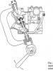
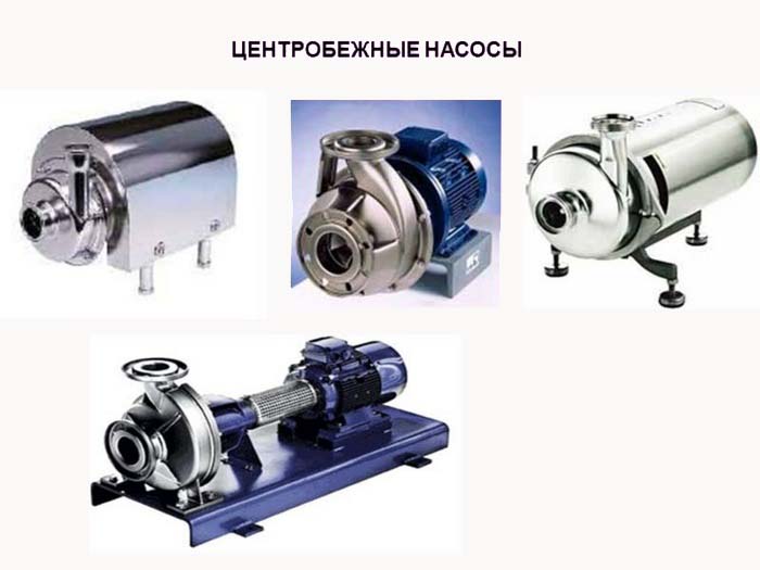
The widespread use of centrifugal pumps in the home and industry is due to their high performance and simplicity of design. For the right choice of installation, consider a centrifugal pump device and the main types.
Pump device
In the spiral case of the unit on the shaft there is an impeller (or several for multi-stage pumps). It represents the front and rear discs (or only the rear), between which there are blades.
The pumped liquid through the suction (receiving) pipe is fed into the central part of the wheel. The shaft is driven by an electric motor. Water due to centrifugal force is pushed from the center of the impeller to its periphery. This creates a rarefied space in the center of the wheel, an area of \u200b\u200blow pressure. This contributes to the influx of new water.
On the periphery of the impeller, on the contrary: water, under pressure, tends to exit through the discharge (discharge) pipe into the pipeline.
Types of Centrifugal Pumps
- By the number of impellers (steps) centrifugal distinguish:
- single-stage - models with one working step (wheel);
- multi-stage - with several wheels on the shaft.
- By the number of impeller disks:
- with front and rear discs - they are used for low pressure networks or for pumping thick liquids;
- with rear disc only.
- :
- horizontal
- vertical.
- By the magnitude of the created water pressure centrifugal pumps are:
- low (up to 0.2 MPa) pressure;
- average (0.2-0.6 MPa) pressure;
- high (from 0.6 MPa pressure).
- By the number and location of suction nozzles:
- with unilateral absorption;
- with bilateral absorption.
- By installation rotation speed:
- high-speed (high-speed) - in these models the impeller is located on the hub;
- normal course;
- slow moving.
- By the method of fluid withdrawal:
- models with a spiral exit - in them water masses are removed directly from the periphery of the blades;
- with a blade exit - the liquid exits through a guiding apparatus with blades.
- According to its purpose:
- sewer;
- plumbing, etc.
- According to the method of connecting the unit with a driving motor:
- using a pulley or gear drive;
- using couplings.
- By installation location during operation:
- surface (external) pumps - during operation they are located on the surface of the earth, and a water intake sleeve is lowered into the tank (cesspool, pit, etc.);
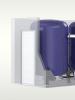
- submersible centrifugal models - such devices are designed for immersion in the pumped liquid;
Types of impellers of a centrifugal pump
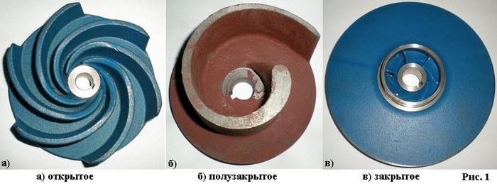
The impeller is one of the important parts of a centrifugal pump. Depending on the power of the unit and its place of work, they differ:
- by material:
- cast iron, steel, copper is used for the manufacture of wheels operating in non-aggressive environments;
- ceramics and similar materials - when the pump is operating in chemically active environments;
- according to the manufacturing method:
- riveted (used for low-power pumps);
- cast;
- stamped;
- in the shape of the blades:
- with straight blades;
- bent to the side opposite to the direction of rotation of the impeller;
- bent in the direction of rotation of the impeller.
The shape of the blades affects the pressure of the water created by the unit.
Working shaft
This is the most susceptible part of the installation to damage during operation. He needs precise balancing and centering. Materials of which the shaft is made:
- forged steel;
- alloy steel (for installations operating with increased loads);
- stainless steel (for use in aggressive environments).
Types of shafts:
- hard (for normal operation);
- flexible (for increased speed);
- connected to the shaft of the drive motor (used for household models of pumps).
The principle of operation of a centrifugal pump, as well as the layout of a centrifugal pump is the same for all types of units. It is based on the power action of rotating blades on the flow of the pumped liquid with the transfer of mechanical energy to it from the working mechanism. The differences in the types of plants are in their power, the created water pressure and design.