What is net power. Full power. Internal resistance of the power supply
The power developed by the current source in the entire circuit is called full power.
It is determined by the formula
where P about is the total power developed by the current source in the entire circuit, W;
E-e. etc. with. source, in;
I is the value of the current in the circuit, a.
In general, the electrical circuit consists of an external section (load) with a resistance R and internal section with resistance R 0(resistance of the current source).

Replacing in the expression for the total power the value of e. etc. with. through the voltages on the sections of the circuit, we get
The quantity UI corresponds to the power developed on the external section of the circuit (load), and is called useful power P floor = UI.
The quantity U o I corresponds to the power wasted inside the source, It is called power loss P o =U o I.
Thus, the apparent power is equal to the sum of the useful power and power losses P about = P floor + P 0.
The ratio of the useful power to the total power developed by the source is called the efficiency, abbreviated to efficiency, and is denoted by η.
The definition implies

Under all conditions, the efficiency is η ≤ 1.
If we express the power through the magnitude of the current and resistance of the sections of the circuit, we get

Thus, the efficiency depends on the ratio between the internal resistance of the source and the resistance of the consumer.
Typically, the electrical efficiency is usually expressed as a percentage.

For practical electrical engineering, two questions are of particular interest:
1. The condition for obtaining the greatest useful power
2. The condition for obtaining the highest efficiency.
The condition for obtaining the highest useful power (power in the load)
The electric current develops the greatest useful power (power at the load) if the load resistance is equal to the resistance of the current source.
This maximum power is equal to half of the total power (50%) developed by the current source in the entire circuit.
Half of the power develops on the load and half develops on the internal resistance of the current source.
If we decrease the load resistance, then the power developed at the load will decrease and the power developed at the internal resistance of the current source will increase.
If the load resistance is zero, then the current in the circuit will be maximum, this is short circuit mode (SC) ... Almost all power will be developed on the internal resistance of the current source. This mode is dangerous for the current source as well as for the entire circuit.
If we increase the load resistance, then the current in the circuit will decrease, the power on the load will also decrease. With a very high load resistance, there will be no current in the circuit at all. This resistance is called infinitely great. If the circuit is open, then its resistance is infinitely large. This mode is called idle mode.
Thus, in modes close to short circuit and to idle, the useful power is small in the first case due to the low voltage value, and in the second due to the small current value.
The condition for obtaining the highest efficiency coefficient of efficiency
The efficiency (efficiency) is equal to 100% at idle (in this case, no useful power is released, but at the same time, the power of the source is not consumed).
As the load current increases, the efficiency decreases according to a straight-line law.
In the short-circuit mode, the efficiency is zero (there is no useful power, and the power developed by the source is completely consumed inside it).
Summing up the above, we can draw conclusions.
The condition for obtaining the maximum useful power (R = R 0) and the condition for obtaining the maximum efficiency (R = ∞) do not coincide. Moreover, when receiving the maximum useful power from the source (matched load mode), the efficiency is 50%, i.e. half of the power developed by the source is wasted inside it.
In powerful electrical installations, the matched load mode is unacceptable, since this is a waste of large power. Therefore, for power plants and substations, the operating modes of generators, transformers, rectifiers are calculated so that a high efficiency is provided (90% or more).
The situation is different in the technique of weak currents. Take a telephone, for example. When talking in front of the microphone, an electrical signal with a power of about 2 mW is generated in the device's circuit. Obviously, in order to obtain the longest communication range, it is necessary to transmit as much power as possible to the line, and for this it is necessary to perform the mode of matched load switching. Does efficiency have a significant value in this case? Of course not, since energy losses are calculated in fractions or units of milliwatts.
The matched load mode is used in radio equipment. In the case when the coordinated mode with the direct connection of the generator and the load is not ensured, measures for matching their resistances are used.
net power- - [Ya.N. Luginsky, M.S.Fezi Zhilinskaya, Y.S.Kabirov. English Russian Dictionary of Electrical Engineering and Power Engineering, Moscow, 1999] net power Power (machinery, equipment, power unit or other technical device) ... ...
Net power- Useful capacity - the power (of a machine, equipment, power unit or other technical device) given by the device in a specific form and for a specific purpose; equal to full power minus costs ... ... Economics and Mathematics Dictionary
net power- 3.10 net power: Effective power in kilowatts obtained on a test bench at the crankshaft shank or measured by the method according to GOST R 41.85. A source … Dictionary-reference book of terms of normative and technical documentation
net power- naudingoji galia statusas T sritis Standartizacija ir metrologija apibrėžtis Galia, susijusi su tam tikros sistemos, įrenginio, aparato ar įtaiso atliekamu naudingu darbu. atitikmenys: angl. net power; useful power vok. Abgabeleistung, f; ... ... Penkiakalbis aiškinamasis metrologijos terminų žodynas
net power- naudingoji galia statusas T sritis fizika atitikmenys: angl. net power; useful power vok. Abgabeleistung, f; Nutzabgabe, f; Nutzleistung, f rus. net power, f pranc. puissance utile, f ... Fizikos terminų žodynas
The power that can be obtained from the motor shaft; same as Effective power ... Great Soviet Encyclopedia
Net power- is the power delivered by the device in a specific form and for a specific purpose. ST IEC 50 (151) 78 ... Commercial power industry. Reference dictionary
net pump power- Power imparted by the pump to the supplied liquid medium and determined by the dependence where Q is the pump flow, m3 / s; P pump pressure, Pa; QM mass flow of the pump, kg / s; LP useful specific work of the pump, J / kg; NP useful power of the pump, W. [GOST ... ... Technical translator's guide
net power (in motor vehicles)- net power Power, expressed in kilowatts, obtained on a test bench at the crankshaft end or its equivalent and measured in accordance with the power measurement method specified in GOST R 41.24. [GOST R 41.49 2003] ... Technical translator's guide
net power in watts- - [A.S. Goldberg. The English Russian Energy Dictionary. 2006] Topics energy in general EN watts out ... Technical translator's guide
When connecting electrical appliances to the mains, usually only the power and efficiency of the electrical appliance itself matter. But when using a current source in a closed circuit, the useful power that it delivers is important. A generator, accumulator, battery or solar power plant elements can be used as a source. For calculations, this is of no fundamental importance.
Power supply parameters
When connecting electrical appliances to the power supply and creating a closed circuit, in addition to the energy P consumed by the load, the following parameters are taken into account:
- Rob. (full power of the current source), allocated in all sections of the circuit;
- EMF - voltage generated by the battery;
- P (useful power) consumed by all sections of the network, except for the current source;
- Ro (power loss) spent inside the battery or generator;
- internal resistance of the battery;
- The efficiency of the power supply.
Attention! The efficiency of the source and the load should not be confused. With a high battery ratio in an electrical appliance, it can be low due to losses in the wires or the device itself, and vice versa.
Total chain energy
When passing electric current heat is released along the chain, or other work is being done. A battery or generator is no exception. The energy released on all elements, including wires, is called total. It is calculated by the formula Rob. = Ro. + Ppol., Where:
- Rob. - full power;
- Ro. - internal losses;
- Rpol. - useful power.

Attention! The concept of total power is used not only in calculating the complete circuit, but also in calculating electric motors and other devices that consume reactive energy together with active reactive energy.
EMF, or electromotive force, is the voltage generated by the source. It can be measured only in the Х.Х mode. (idle move). When the load is connected and the current appears, Uо is subtracted from the EMF value. - voltage losses inside the power supply.

Net power
Useful is the energy released in the entire circuit, except for the power supply. It is calculated by the formula:
- “U” - voltage at the terminals,
- “I” is the current in the circuit.
In a situation in which the load resistance is equal to the resistance of the current source, it is maximum and equal to 50% of the full.
With a decrease in the load resistance, the current in the circuit increases along with internal losses, and the voltage continues to fall, and when it reaches zero, the current will be maximum and limited only by Rо. This is the K.Z. - short circuit. In this case, the energy of losses is equal to the total.
With an increase in the load resistance, the current and internal losses fall, and the voltage rises. When an infinitely large value is reached (network break) and I = 0, the voltage will be equal to the EMF. This is the X..X mode. - idle move.
Loss inside the power supply
Batteries, generators and other devices have internal resistance. When current flows through them, energy losses are released. It is calculated by the formula:
where “Uо” is the voltage drop inside the device or the difference between the EMF and the output voltage.
Internal resistance of the power supply
To calculate the loss of Ro. it is necessary to know the internal resistance of the device. This is the resistance of the generator windings, the electrolyte in the battery, or for other reasons. It is not always possible to measure it with a multimeter. You have to use indirect methods:
- when the device is turned on in idle mode, E (EMF) is measured;
- when the load is connected, Uout is determined. (output voltage) and current I;
- the voltage drop inside the device is calculated:
- internal resistance is calculated:
Useful energy P and efficiency
Depending on the specific tasks, the maximum net power P or the maximum efficiency is required. The conditions for this are not the same:
- P is maximum at R = Ro, while efficiency = 50%;
- The efficiency is 100% in the H.H. mode, while P = 0.

Getting maximum energy at the output of the power supply
The maximum P is achieved provided that the resistances R (load) and Ro (source of electricity) are equal. In this case, efficiency = 50%. This is a "matched load" mode.
In addition to it, two options are possible:
- The resistance R falls, the current in the circuit increases, while the voltage losses Uo and Po inside the device increase. In short circuit mode (short circuit) the load resistance is “0”, I and Po are maximum, and the efficiency is also 0%. This mode is dangerous for batteries and generators, therefore it is not used. The exception is practically obsolete welding generators and car batteries, which, when starting the engine and turning on the starter, operate in a mode close to "KZ";
- The load resistance is greater than the internal one. In this case, the current and power of the load P fall, and with an infinitely large resistance, they are equal to “0”. This is the H.H. (idle move). Internal losses in a mode close to H.H. are very small, and the efficiency is close to 100%.
Consequently, “P” is maximum when the internal and external resistances are equal and is minimum in other cases due to high internal losses at short circuit and low current in the Kh.Kh. mode.
The mode of maximum usable power at an efficiency of 50% is used in electronics at low currents. For example, in the telephone set Pout. microphone - 2 milliwatts, and it is important to transfer it to the network as much as possible, sacrificing efficiency.
Achieving maximum efficiency
The maximum efficiency is achieved in the Х.Х mode. due to the absence of power losses inside the voltage source Po. With an increase in the load current, the efficiency decreases linearly in the short-circuit mode. equals “0”. The maximum efficiency mode is used in power plant generators where matched load, maximum net Po and 50% efficiency are not applicable due to large losses that account for half of the total energy.
Load efficiency
The efficiency of electrical appliances is independent of the battery and never reaches 100%. The exception is air conditioners and refrigerators operating on the principle heat pump: one radiator is cooled by heating another. If this moment is not taken into account, then the efficiency is above 100%.
Energy is spent not only on doing useful work, but also on heating wires, friction and other types of losses. In luminaires, in addition to the efficiency of the lamp itself, attention should be paid to the design of the reflector, in air heaters - to the efficiency of heating the room, and in electric motors - to cos φ.
Knowing the useful power of the power supply element is necessary to perform calculations. Without this, it is impossible to achieve maximum efficiency of the entire system.
Video
 (12.11)
A short circuit is a mode of operation of a circuit in which an external resistance R= 0. Moreover,
 (12.12)
Net power R but = 0.
Full power
 (12.13)
Dependency graph R but (I) - a parabola, the branches of which are directed downward (Figure 12.1). The same figure shows the dependence of the efficiency on the strength of the current.

Examples of problem solving
Objective 1. The battery consists of n= 5 elements connected in series with E= 1.4 V and internal resistance r= 0.3 ohms each. At what current is the useful power of the battery equal to 8 W? What is the maximum net wattage of the battery?
Given: Decision
n = 5 When the elements are connected in series, the current in the circuit
E= 1.4V  (1)
(1)
R but= 8 W From the effective power formula  express
external resistance R and substitute in formula (1)
I
-
?
 -?
-? 
after transformations, we get a quadratic equation, solving which, we find the value of the currents:


 BUT; I 2
=
BUT; I 2
=
 A.
A.
So, at currents I 1 and I 2, the net power is the same. When analyzing the graph of the dependence of the useful power on the current, it can be seen that at I 1, the power loss is less and the efficiency is higher.
Useful power is maximum at R
=
n
r;
R
= 0,3 Ohm.
Ohm.


Answer:
I 1 = 2 A; I 2
=
 A; P amax =
  Tue
Tue
Objective 2. The useful power released in the outer part of the circuit reaches the maximum value of 5 W at a current of 5 A. Find the internal resistance and EMF of the current source.
Given: Decision
P amax = 5 W Net power 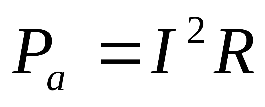 (1)
(1)
I= 5 A according to Ohm's law  (2)
(2)
Useful power is maximum at R = r then from
r
- ? E-? formulas (1)  0.2 ohm.
From formula (2) V.
Answer: r= 0.2 ohm; E= 2 V.
Objective 3. From a generator with an EMF equal to 110V, it is required to transmit energy over a distance of 2.5 km along a two-wire line. The power consumption is 10 kW. Find the minimum cross-section of copper lead wires if the power loss in the network should not exceed 1%.
Given: Decision
E = 110V Wire Resistance 
l= 510 3 m where - resistivity of copper; l- the length of the wires;
R but = 10 4 W S- section.
= 1.710 -8 Ohm. m Power consumption P a = I E, power lost
R etc = 100 W on the network P etc = I 2 R etc, and since in breeds and consumer
S - ? current the same then

from where 
Substituting the numerical values, we get
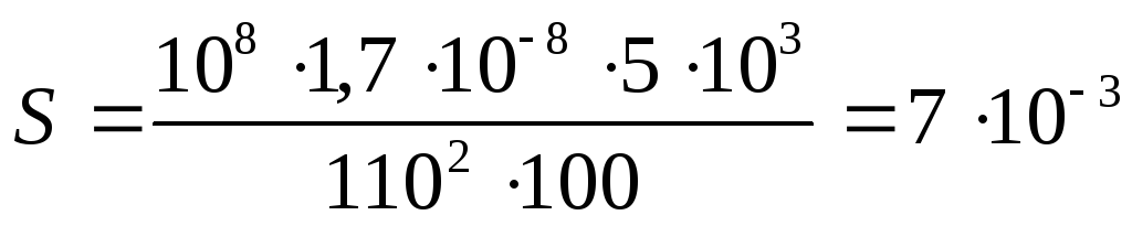 m 2.
m 2.
Answer: S= 710 -3 m 2.
Task 4. Find the internal resistance of the generator if it is known that the power released in the external circuit is the same for two values of the external resistance R 1 = 5 ohms and R 2 = 0.2 ohm. Find the generator efficiency in each of these cases.
Given: Decision
R 1 = R 2 Power allocated in the external circuit, P a = I 2 R... Ohm's law
R 1 = 5 Ohm for closed circuit  then
then  .
.
R 2 = 0.2 Ohm Using Problem Condition R 1 = R 2, we get
r
-?


Transforming the obtained equality, we find the internal resistance of the source r:
 Ohm.
Ohm.
The efficiency is the quantity
 ,
,
Where R but- power released in the external circuit; R- full power.
Answer:
r= 1 Ohm;  =
83 %;
=
83 %; =
17 %.
=
17 %.
Task 5. Battery EMF E= 16 V, internal resistance r= 3 ohms. Find the resistance of the external circuit if it is known that power is released in it R but= 16 W. Determine the efficiency of the battery.
Given: Decision
E= 16 V Power dissipated in the outer part of the circuit R but = I 2 R.
r
=
3 Ohm We find the current strength according to Ohm's law for a closed circuit: 
R but= 16 W then  or
or 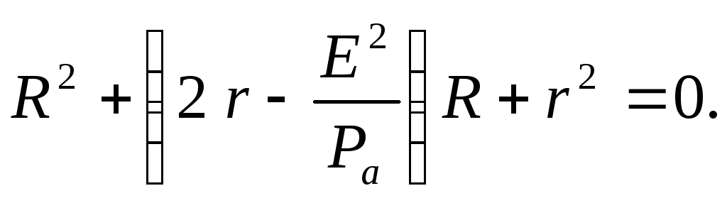
- ? R-? Substitute the numerical values of the given quantities into this quadratic equation and solve it with respect to R:
Ohm; R 2 = 9 ohms.
Answer: R 1 = 1 ohm; R 2 = 9 ohms;
Task 6. Two light bulbs are connected to the network in parallel. The resistance of the first light bulb is 360 ohms, the resistance of the second one is 240 ohms. Which of the bulbs absorbs the most power? How many times?
Given: Decision
R 1 = 360 Ohm The power dissipated in the light bulb,
R 2 = 240 Ohm P = I 2 R (1)
 -
?
With a parallel connection, the bulbs will have the same voltage, therefore, it is better to compare the powers by transforming formula (1) using Ohm's law
-
?
With a parallel connection, the bulbs will have the same voltage, therefore, it is better to compare the powers by transforming formula (1) using Ohm's law  then
then 

When light bulbs are connected in parallel, more power is released in a light bulb with less resistance.
Answer:

Task 7. Two consumers with resistances R 1 = 2 ohms and R 2 = 4 ohms are connected to the DC mains the first time in parallel and the second time in series. When is a lot of power consumed from the mains? Consider the case where R 1 = R 2 .
Given: Decision
R 1 = 2 Ohm Mains power consumption
R 2 = 4 ohm  (1)
(1)
 -
?
Where R- general resistance of consumers; U- mains voltage. When consumers are connected in parallel, their total resistance
-
?
Where R- general resistance of consumers; U- mains voltage. When consumers are connected in parallel, their total resistance  and with consistent R
= R 1
+ R 2 .
and with consistent R
= R 1
+ R 2 .
In the first case, according to formula (1), the power consumption  and in the second
  from where

Thus, when the loads are connected in parallel, more power is consumed from the network than when connected in series.
When 
Answer:

Task 8.... The boiler heater consists of four sections, the resistance of each section R= 1 ohm. The heater is powered by a rechargeable battery E = 8 B and internal resistance r= 1 ohm. How to connect the heater elements so that the water in the boiler heats up to the maximum short term? What is the total power consumed by the battery and its efficiency?
Given:
R 1 = 1 ohm
E = 8 in
r= 1 ohm

Decision
The source gives the maximum useful power if the external resistance R equal to internal r.
Therefore, in order for water to heat up as soon as possible, you need to turn on the sections so that
so that R = r... This condition is fulfilled with a mixed connection of sections (Figure 12.2.a, b).
The power consumed by the battery is R
= I
E... Ohm's law for a closed circuit  then
then 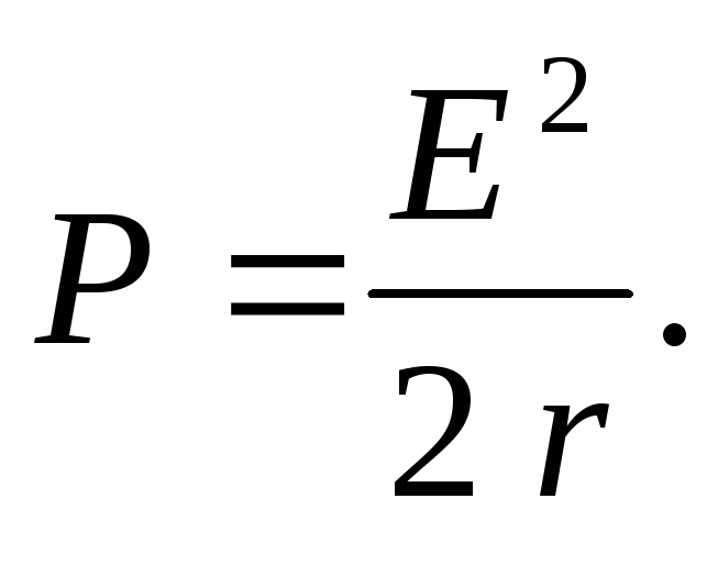
Let's calculate  32 watts;
Answer: R= 32 W; = 50 %.
Problem 9 *. Resistance conductor current R= 12 Ohm decreases steadily from I 0 = 5 A to zero over time = 10 s. How much heat is released in the conductor during this time?
Given:
R= 12 Ohm
I 0 = 5 A
Q - ?
DecisionSince the current in the conductor changes, then to calculate the amount of heat by the formula Q = I 2 R t can not be used.
Let's take a differential dQ
=
I
2 R
dt then  Due to the uniformity of the current change, we can write I
=
k
t where k- coefficient of proportionality.
Due to the uniformity of the current change, we can write I
=
k
t where k- coefficient of proportionality.

Proportionality factor value k we find from the condition that for
= 10 s current I 0 = 5 A, I 0
= k
, from here 

Substitute the numerical values:
 J.
J.
Answer: Q= 1000 J.
OHM'S LAW FOR THE FULL CHAIN:
I is the current in the circuit; E is the electromotive force of the current source included in the circuit; R is the resistance of the external circuit; r is the internal resistance of the current source.
POWER RELEASED IN THE EXTERNAL CIRCUIT
![]() . (2)
. (2)
From formula (2) it can be seen that with a short circuit of the circuit ( R®0) and for R® this cardinality is equal to zero. For all other end values R power R 1> 0. Therefore, the function R 1 has a maximum. Value R 0, corresponding to the maximum power, can be obtained by differentiating P 1 with respect to R and equating the first derivative to zero:
 . (3)
. (3)
From formula (3), taking into account that R and r are always positive, and E? 0, after simple algebraic transformations we get:
Hence, the power released in the external circuit reaches its maximum value when the resistance of the external circuit is equal to the internal resistance of the current source.
In this case, the current in the circuit (5)
equal to half the short-circuit current. In this case, the power released in the external circuit reaches its maximum value equal to
When the source is closed to an external resistance, then the current flows inside the source and at the same time a certain amount of heat is released on the internal resistance of the source. The power spent on the release of this heat is
Therefore, the total power released in the entire circuit is determined by the formula
= I 2(R + r) = IE (8)
EFFICIENCY
EFFICIENCY current source is ![]() . (9)
. (9)
From formula (8) it follows that
those. R 1 changes with a change in the current in the circuit according to the parabolic law and takes zero values at I = 0 and at. The first value corresponds to an open circuit (R >> r), the second to a short circuit (R<< r). Зависимость к.п.д. от силы тока в цепи с учётом формул (8), (9), (10) примет вид
Thus, the efficiency is reaches the maximum value h = 1 in the case of an open circuit (I = 0), and then decreases linearly, turning to zero in the case of a short circuit.
Dependence of capacities Р 1, Р total = EI and efficiency. the current source from the current in the circuit are shown in Fig. 1.

Fig. 1. I 0 E / r
It can be seen from the graphs that it is possible to simultaneously obtain useful power and efficiency. impossible. When the power released in the outer section of the P 1 circuit reaches the highest value, the efficiency is at this moment is equal to 50%.
MEASUREMENT PROCEDURE AND PROCEDURE

Assemble the circuit shown in fig. 2. To do this, first left-click on the e.m.f. button. at the bottom of the screen. Move the mouse marker to the working area of the screen, where the points are located. Left-click in the working area of the screen, where the source of emf will be located.
Place further in series with the source a resistor representing its internal resistance (by first pressing the button at the bottom of the screen) and an ammeter (button in the same place). Then position the load resistors and a voltmeter that measures the voltage across the load in the same way.
Connect the connecting wires. To do this, click the wire button at the bottom of the screen, and then move the mouse marker to the working area of the circuit. Click the left mouse button in the places of the working area of the screen, where the connecting wires should be.
4. Set parameter values for each item. To do this, left-click on the arrow button. Then click on this item. Move the mouse marker to the slider of the appeared regulator, press and hold the left mouse button, change the parameter value and set the numerical value indicated in Table 1 for your variant.
Table 1. Initial parameters of the electrical circuit
|
option |
||||||||
5. Set the resistance of the external circuit to 2 Ohm, press the "Count" button and write down the readings of electrical measuring instruments in the corresponding lines of Table 2.
6. Using the regulator slider, increase the resistance of the external circuit by 0.5 Ohm from 2 Ohm to 20 Ohm in succession and, pressing the "Count" button, write down the readings of electrical measuring instruments in Table 2.
7. Calculate by the formulas (2), (7), (8), (9) Р 1, Р 2, Р total and h for each pair of voltmeter and ammeter readings and record the calculated values in Table 2.
8. Build on one sheet of graph paper the graphs of the dependence P 1 = f (R), P 2 = f (R), P full = f (R), h = f (R) and U = f (R).
9. Calculate the measurement error and draw conclusions based on the results of the experiments.
Table 2. Results of measurements and calculations
|
P full, W |
|||||||
Questions and tasks for self-control
- Write down the Joule-Lenz law in integral and differential forms.
- What is short circuit current?
- What is Apparent Power?
- How is efficiency calculated? current source?
- Prove that the greatest useful power is released when the external and internal resistances of the circuit are equal.
- Is it true that the power released in the internal part of the circuit is constant for a given source?
- A voltmeter was connected to the terminals of the flashlight battery, which showed 3.5 V.
- Then the voltmeter was disconnected and a lamp was connected in its place, on the base of which it was written: P = 30 W, U = 3.5 V. The lamp did not burn.
- Explain the phenomenon.
- With the alternate closure of the battery to the resistances R1 and R2, an equal amount of heat was released in them for the same time. Determine the internal resistance of the battery.