Information about gas turbines. The principle of operation of gas turbines What does the approval of the efficiency of a gas turbine mean 40
A turbine is an engine in which the potential energy of a compressible fluid is converted into kinetic energy in the blade apparatus, and the latter in the impellers into mechanical work transmitted to a continuously rotating shaft.
Steam turbines by their design represent a heat engine that is constantly in operation. During operation, superheated or saturated water vapor enters the flow path and, due to its expansion, forces the rotor to rotate. Rotation occurs as a result of the steam flow acting on the blade apparatus.
The steam turbine is part of the steam turbine design, which is designed to generate energy. There are also installations that, in addition to electricity, can generate thermal energy - the steam that has passed through the steam blades enters the network water heaters. This type of turbine is called the industrial heating or heating type of turbines. In the first case, steam extraction is provided for industrial purposes in the turbine. Complete with a generator, a steam turbine is a turbine unit.
Steam turbine types
Turbines are divided, depending on the direction in which the steam moves, into radial and axial turbines. The steam flow in radial turbines is directed perpendicular to the axis. Steam turbines can be one-, two- and three-case. The steam turbine is equipped with a variety of technical devices that prevent the ingress of ambient air into the casing. These are a variety of seals, which are supplied with water vapor in a small amount.
A safety regulator is located on the front section of the shaft, designed to turn off the steam supply when the turbine speed increases.
Characteristics of the main parameters of the nominal values
· Turbine rated power- the maximum power that the turbine must develop for a long time at the terminals of the electric generator, with normal values of the main parameters or when they change within the limits specified by industry and state standards. A controlled steam extraction turbine can develop power above its nominal power if this is in accordance with the strength conditions of its parts.
· Turbine economic power- the power at which the turbine operates with the greatest efficiency. Depending on the parameters of live steam and the purpose of the turbine, the rated power can be equal to the economic power or more by 10-25%.
· Nominal temperature of regenerative feed water heating- the temperature of the feed water downstream of the last heater in the direction of the water.
· Rated cooling water temperature- the temperature of the cooling water at the inlet to the condenser.
gas turbine(fr. turbine from lat. turbo swirl, rotation) is a continuous heat engine, in the blade apparatus of which the energy of compressed and heated gas is converted into mechanical work on the shaft. It consists of a rotor (blades fixed on disks) and a stator (guide vanes fixed in the housing).
Gas having a high temperature and pressure enters through the turbine nozzle apparatus into the low pressure area behind the nozzle part, simultaneously expanding and accelerating. Further, the gas flow enters the turbine blades, giving them part of its kinetic energy and imparting torque to the blades. The rotor blades transmit torque through the turbine discs to the shaft. Useful properties of a gas turbine: a gas turbine, for example, drives a generator located on the same shaft with it, which is the useful work of a gas turbine.
Gas turbines are used as part of gas turbine engines (used for transport) and gas turbine units (used at thermal power plants as part of stationary GTUs, CCGTs). Gas turbines are described by the Brayton thermodynamic cycle, in which air is first adiabatically compressed, then burned at constant pressure, and then adiabatically expanded back to starting pressure.
Types of gas turbines
- Aircraft and jet engines
- Auxiliary power unit
- Industrial gas turbines for electricity generation
- Turboshaft engines
- Radial gas turbines
- Microturbines
Mechanically, gas turbines can be considerably simpler than reciprocating internal combustion engines. Simple turbines may have one moving part: shaft/compressor/turbine/alternate rotor assembly (see image above), not including the fuel system.
More complex turbines (those used in modern jet engines) may have multiple shafts (coils), hundreds of turbine blades, moving stator blades, and an extensive system of complex piping, combustion chambers, and heat exchangers.
As a general rule, the smaller the motor, the higher the speed of the shaft(s) required to maintain the maximum linear speed of the blades. The maximum speed of the turbine blades determines the maximum pressure that can be reached, resulting in maximum power, regardless of engine size. The jet engine rotates at about 10,000 rpm and the micro-turbine at about 100,000 rpm.
Power plants of relatively small capacity can include both gas turbine engines (GTE) and reciprocating engines (RP). As a result, customers often ask which drive is better. And, although it is unambiguously impossible to answer it, the purpose of this article is an attempt to understand this issue.
Introduction
The choice of the type of engine, as well as their number for driving electric generators at a power plant of any capacity, is a complex technical and economic task. Attempts to compare piston and gas turbine engines as a drive are most often made using natural gas as a fuel. Their fundamental advantages and disadvantages have been analyzed in the technical literature, in the brochures of manufacturers of power plants with piston engines, and even on the Internet.
As a rule, generalized information is given about the difference in fuel consumption, in the cost of engines, without taking into account their power and operating conditions. It is often noted that it is preferable to form the composition of power plants with a capacity of 10-12 MW on the basis of reciprocating engines, and higher power - on the basis of gas turbines. These recommendations should not be taken as an axiom. One thing is obvious: each type of engine has its advantages and disadvantages, and when choosing a drive, some, at least indicative, quantitative criteria for their evaluation are needed.
Currently, the Russian energy market offers a fairly wide range of both reciprocating and gas turbine engines. Among piston engines, imported engines prevail, and among gas turbine engines, domestic ones.
Information about the technical characteristics of gas turbine engines and power plants based on them, proposed for operation in Russia, has been regularly published in the "Catalogue of gas turbine equipment" in recent years.
Similar information about reciprocating engines and power plants, which they are part of, can only be obtained from advertising brochures of Russian and foreign companies that supply this equipment. Information about the cost of engines and power plants is most often not published, and published information is often not true.
Head-to-Head Comparison of Reciprocating and Gas Turbine Engines
The processing of the available information makes it possible to form the table below, which contains both a quantitative and a qualitative assessment of the advantages and disadvantages of reciprocating and gas turbine engines. Unfortunately, some of the characteristics are taken from promotional materials, the complete accuracy of which is extremely difficult or almost impossible to verify. The data required for verification on the results of the operation of individual engines and power plants, with rare exceptions, are not published.
Naturally, the figures given are generalized; for specific engines, they will be strictly individual. In addition, some of them are given in accordance with ISO standards, and the actual operating conditions of the engines differ significantly from the standard.
The presented information gives only a qualitative characteristic of the engines and cannot be used when selecting equipment for a particular power plant. Some comments can be given for each position of the table.
| Indicator | engine's type | |
|---|---|---|
| Piston | gas turbine | |
| Engine unit power range (ISO), MW | 0.1 - 16.0 | 0.03 - 265.0 |
| Power change at constant outdoor temperature | More stable when the load is reduced by 50%. Efficiency is reduced by 8-10% | Less stable when the load is reduced by 50%. Efficiency is reduced by 50% |
| Influence of outdoor temperature on engine power | Virtually no effect | When the temperature drops to -20°C, the power increases by about 10-20%, when it rises to +30°C, it decreases by 15-20% |
| Effect of outdoor temperature on engine efficiency | Virtually no effect | When the temperature drops to -20°C, the efficiency increases by about 1.5% abs. |
| Fuel | gaseous, liquid | Gaseous, liquid (by special order) |
| Required fuel gas pressure, MPa | 0.01 - 0.035 | Over 1.2 |
| Gas Power Generation Efficiency (ISO) | from 31% to 48% | In a simple cycle from 25% to 38%, in a combined cycle - from 41% to 55% |
| Ratio of electric power and amount of utilized heat, MW/MW (ISO) | 1/(0.95-1.3) | 1/(1.4-4.0) |
| Possibilities of using the recovered heat of exhaust gases | Only for heating water above 115°C | For the production of steam for power generation, refrigeration, water desalination, etc., for heating water up to a temperature of 150°C |
| Influence of outdoor air temperature on the amount of heat recovered | Virtually no effect | With a decrease in air temperature, the amount of heat in the presence of an adjustable blade apparatus of a gas turbine almost does not decrease, in its absence it decreases |
| Motor resource, h | More: up to 300,000 for medium speed engines | Less: up to 100,000 |
| Rate of increase in operating costs with increasing service life | Less tall | Higher |
| Mass of the power unit (engine with electric generator and auxiliary equipment), kg/kW | Significantly higher: 22.5 | Significantly lower: 10 |
| Power unit dimensions, m | More: 18.3x5.0x5.9 with a unit power of the unit 16MW without a cooling system | Less: 19.9x5.2x3.8 with a unit power of the unit 25MW |
| Specific oil consumption, g/kW*h | 0.3 - 0.4 | 0.05 |
| Number of starts | Not limited and does not affect the reduction of motor resources | Not limited, but affects the reduction of motor resource |
| maintainability | Repairs can be done on site and require less time | Repair is possible at a special enterprise |
| Overhaul cost | Cheaper | More expensive |
| Ecology | Specifically - in mg / m3 - more, but the amount of harmful emissions in m3 is less | Specific - in mg/m3 - less, but the volume of emissions in m3 is higher |
| Unit cost | Less with unit motor power up to 3.5 MW | Less with a unit motor power of more than 3.5 MW |
The energy market has a very large selection of engines with significant differences in technical characteristics. Competition between the engines of the considered types is possible only in the range of unit electric power up to 16 MW. At higher powers, gas turbine engines replace piston engines almost completely.
It must be taken into account that each motor has individual characteristics, and only these should be used when choosing a drive type. This makes it possible to form the composition of the main equipment of a power plant of a given capacity in several versions, varying, first of all, the electric power and the number of required engines. The versatility makes it difficult to choose the preferred type of engine.
On the efficiency of piston and gas turbine engines
The most important characteristic of any engine in power plants is the power generation efficiency (KPIe), which determines the main, but not the full volume of gas consumption. The processing of statistical data on the values of efficiency makes it possible to clearly show the areas of application in which, according to this indicator, one type of engine has advantages over another.

The mutual arrangement and configuration of the three selected in Fig. 1 zones, within which there are dot images of the values of the electrical efficiency of various engines, allows us to draw some conclusions:
- even within the same type of engines of the same power, there is a significant scatter in the values of efficiency for generating electricity;
- with a unit power of more than 16 MW, gas turbine engines in the combined cycle provide an efficiency value of more than 48% and monopolize the market;
- electrical efficiency of gas turbine engines up to 16 MW, operating in both simple and combined cycles, is lower (sometimes very significantly) than that of piston engines;
- gas turbine engines with a unit capacity of up to 1 MW, which have recently appeared on the market, are superior in terms of efficiency to engines with a capacity of 2-8 MW, which are most often used today in power plants;
- the nature of the change in the efficiency of gas turbine engines has three zones: two with a relatively constant value - 27 and 36%, respectively, and one with a variable - from 27 to 36%; within two zones, the efficiency coefficient weakly depends on the electric power;
- the value of the efficiency for the generation of electricity of reciprocating engines is in constant dependence on their electrical power.
However, these factors are not a reason to give priority to piston engines. Even if the power plant will produce only electrical energy, when comparing equipment options with different types of engines, it will be necessary to perform economic calculations. It is necessary to prove that the cost of saved gas will pay for the difference in the cost of reciprocating and gas turbine engines, as well as additional equipment for them. The amount of saved gas cannot be determined if the operating mode of the station for the supply of electricity in winter and summer is unknown. Ideally, if the necessary electrical loads are known - maximum (winter working day) and minimum (summer day off).
Use of both electrical and thermal energy
If the power plant must produce not only electrical, but also thermal energy, then it will be necessary to determine from which sources it is possible to cover heat consumption. As a rule, there are two such sources - the utilized heat of engines and/or the boiler house.
For piston engines, the heat of the cooling oil, compressed air and exhaust gases is utilized, for gas turbine engines only the heat of the exhaust gases is utilized. The main amount of heat is recovered from the exhaust gases with the help of waste heat exchangers (UHE).
The amount of recovered heat largely depends on the mode of operation of the engine to generate electricity and on climatic conditions. Incorrect assessment of the engine operation modes in winter will lead to errors in determining the amount of utilized heat and an incorrect choice of the installed capacity of the boiler house.
Graphs in Fig. 2 show the possibility of reclaimed heat supply from gas turbine and piston engines for heat supply purposes. The points on the curves correspond to the manufacturer's data on the capabilities of the available equipment for heat recovery. On the engine of the same electric power, manufacturers install various UTOs - based on specific tasks.

The advantages of gas turbine engines in terms of heat generation are undeniable. This is especially true for motors with an electric power of 2-10 MW, which is explained by the relatively low value of their electrical efficiency. As the efficiency of gas turbine engines increases, the amount of utilized heat must inevitably decrease.
When choosing a piston engine for power and heat supply of a particular facility, the need to use a boiler house as part of a power plant is almost beyond doubt. The operation of the boiler house requires an increase in gas consumption in excess of what is necessary to generate electricity. The question arises of how the gas costs for the energy supply of the facility differ if in one case only gas turbine engines with exhaust heat recovery are used, and in the other case piston engines with heat recovery and a boiler house are used. Only after a thorough study of the features of the object's consumption of electricity and heat can this question be answered.
If we assume that the estimated heat consumption of an object can be completely covered by the utilized heat of the gas turbine engine, and the lack of heat when using a piston engine is compensated by the boiler house, then it is possible to identify the nature of the change in the total gas consumption for the energy supply of the object.
Using the data in Fig. 1 and 2, it is possible for the characteristic points of the zones marked in Figs. 1, get information about gas savings or overruns when using various types of actuators. They are presented in the table:
The absolute values of gas savings are valid only for a specific object, the characteristics of which were included in the calculation, but the general nature of the dependence is reflected correctly, namely:
with relatively close values of electrical efficiency (difference up to 10%), the use of piston engines and a boiler room leads to excessive fuel consumption;
- with relatively close values of electrical efficiency (difference up to 10%), the use of piston engines and a boiler room leads to excessive fuel consumption;
- with a difference in efficiency values of more than 10%, the operation of reciprocating engines and the boiler house will require less gas than for gas turbine engines;
- there is a certain point with maximum gas savings when using reciprocating engines and a boiler room, where the difference between the efficiency values of engines is 13-14%;
- the higher the efficiency of a reciprocating engine and the lower the efficiency of a gas turbine, the greater the gas savings.
As a supplement
As a rule, the task is not limited to the choice of the type of drive, it is required to determine the composition of the main equipment of the power plant - the type of units, their number, auxiliary equipment.
The choice of engines to produce the right amount of electricity determines the possibilities for generating recovered heat. In this case, it is necessary to take into account all the features of changes in the technical characteristics of the engine associated with climatic conditions, with the nature of the electrical load, and determine the effect of these changes on the supply of utilized heat.
It must also be remembered that the power plant includes not only engines. On its site, there are usually more than a dozen auxiliary structures, the operation of which also affects the technical and economic performance of the power plant.
As already mentioned, from a technical point of view, the composition of the power plant equipment can be formed in several ways, so its final choice can only be justified from an economic standpoint.
At the same time, knowledge of the characteristics of specific engines and their impact on the economic performance of a future power plant is extremely important. When performing economic calculations, it is inevitable to take into account the motor resource, maintainability, timing and cost of major repairs. These indicators are also individual for each specific engine, regardless of its type.
The influence of environmental factors on the choice of the type of engines for the power plant cannot be ruled out. The state of the atmosphere in the area where the power plant is to be operated can be a major factor in determining the type of engine (regardless of any economic considerations).
As already noted, data on the cost of engines and power plants based on them are not published. Manufacturers or suppliers of equipment refer to the possible difference in configuration, delivery conditions and other reasons. Prices will be presented only after filling in the corporate questionnaire. Therefore, the information in the first table that the cost of reciprocating engines with a power of up to 3.5 MW is lower than the cost of gas turbine engines of the same power may turn out to be incorrect.
Conclusion
Thus, in the unit power class up to 16 MW, neither gas turbine nor piston engines can be given unequivocal preference. Only a thorough analysis of the expected modes of operation of a particular power plant for the generation of electricity and heat (taking into account the characteristics of specific engines and numerous economic factors) will fully justify the choice of engine type. A specialized company can determine the composition of the equipment at a professional level.
References
- Gabich A. Application of gas turbine engines of low power in the energy sector // Gas turbine technologies. 2003, No. 6. S. 30-31.
- Burov VD Gas-turbine and gas-piston power plants of low power // Mining magazine. 2004, special issue. pp. 87-89,133.
- Catalog of gas turbine equipment // Gas turbine technologies. 2005. S. 208.
- Salikhov A. A., Fatkulin R. M., Abrakhmanov R. R., Shchaulov V. Yu. Development of mini-CHP with the use of gas piston engines in the Republic of Bashkortostan. 2003, No. 11. S. 24-30.
This article, with minor changes, is taken from the journal "Turbines and Diesels", No. 1 (2) for 2006.
Author - V.P. Vershinsky, OOO "Gazpromenergoservis".
Gritsyna V.P.
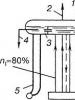
In connection with the multiple growth of electricity tariffs in Russia, many enterprises are considering the construction of their own low-capacity power plants. In a number of regions, programs are being developed for the construction of small or mini thermal power plants, in particular, as a replacement for obsolete boiler houses. At a new small CHP plant with a fuel utilization rate of up to 90% with full use of the body in production and for heating, the cost of electricity received can be significantly lower than the cost of electricity received from the power grid.
When considering projects for the construction of small thermal power plants, power engineers and specialists of enterprises are guided by the indicators achieved in the large power industry. Continuous improvement of gas turbines (GTUs) for use in large-scale power generation has made it possible to increase their efficiency to 36% or more, and the use of a combined steam-gas cycle (CCGT) has increased the electrical efficiency of TPPs to 54% -57%.
However, in the small-scale power industry it is inappropriate to consider the possibility of using complex schemes of combined cycles of CCGT for the production of electricity. In addition, gas turbines, in comparison with gas engines, as drives for electric generators, lose significantly in terms of efficiency and performance, especially at low powers (less than 10 MW). Since in our country neither gas turbines nor gas piston engines have yet been widely used in small-scale stationary power generation, the choice of a specific technical solution is a significant problem.
This problem is also relevant for large-scale energy, i.e. for power systems. In modern economic conditions, in the absence of funds for the construction of large power plants on obsolete projects, which can already be attributed to the domestic project of a 325 MW CCGT, designed 5 years ago. Energy systems and RAO UES of Russia should pay special attention to the development of small-scale power generation, at whose facilities new technologies can be tested, which will make it possible to begin the revival of domestic turbine-building and machine-building plants and, in the future, move to large capacities.
In the last decade, large diesel or gas engine thermal power plants with a capacity of 100-200 MW have been built abroad. The electrical efficiency of diesel or gas-powered power plants (DTPP) reaches 47%, which exceeds the performance of gas turbines (36%-37%), but is inferior to those of CCGT (51%-57%). CCGT power plants include a large range of equipment: a gas turbine, a waste heat steam boiler, a steam turbine, a condenser, a water treatment system (plus a booster compressor if low or medium pressure natural gas is burned. Diesel generators can run on heavy fuel, which is 2 times cheaper than gas turbine fuel and can operate on low-pressure gas without the use of booster compressors.According to SEMT PIELSTICK, the total cost of operating a diesel power unit with a capacity of 20 MW over 15 years is 2 times less than for a gas turbine thermal power plant of the same capacity when using liquid fuel by both power plants.
A promising Russian manufacturer of diesel power units up to 22 MW is the Bryansk Machine-Building Plant, which offers customers power units with increased efficiency up to 50% for operation both on heavy fuel with a viscosity of up to 700 cSt at 50 C and a sulfur content of up to 5%, and for operation on gaseous fuel.
The option of a large diesel thermal power plant may be preferable to a gas turbine power plant.
In small-scale power generation, with unit capacities of less than 10 MW, the advantages of modern diesel generators are even more pronounced.
Let us consider three variants of thermal power plants with gas turbine plants and gas piston engines.
The fuel utilization factor for the first two options of power plants (with different electrical efficiency) due to heat supply can reach 80% -94%, both in the case of gas turbines and for motor drives.
The profitability of all variants of power plants depends on the reliability and efficiency, first of all, of the "first stage" - the drive of the electric generator.
Enthusiasts for the use of small gas turbines are campaigning for their widespread use, noting the higher power density. For example, in [1] it is reported that Elliot Energy Systems (in 1998-1999) is building a distribution network of 240 distributors in North America providing engineering and service support for the sale of "micro" gas turbines. The power grid ordered a 45 kW turbine to be ready for delivery in August 1998. It also stated that the electrical efficiency of the turbine was as high as 17%, and noted that gas turbines were more reliable than diesel generators.
This statement is exactly the opposite!
If you look at Table. 1. then we will see that in such a wide range from hundreds of kW to tens of MW, the efficiency of the motor drive is 13% -17% higher. The indicated resource of the motor drive of the company "Vyartsilya" means a guaranteed resource until a complete overhaul. The resource of new gas turbines is a calculated resource, confirmed by tests, but not by statistics of work in real operation. According to numerous sources, the resource of gas turbines is 30-60 thousand hours with a decrease with a decrease in power. The resource of diesel engines of foreign production is 40-100 thousand hours or more.
Table 1
Main technical parameters of electric generator drives
G-gas-turbine power plant, D-gas-piston generating plant of Vyartsilya.
D - diesel from the Gazprom catalog
* The minimum value of the required pressure of the fuel gas = 48 ATA!!
Performance characteristics
Electrical efficiency (and power) According to Värtsilä data, when the load is reduced from 100% to 50%, the efficiency of an electric generator driven by a gas engine changes little.
The efficiency of a gas engine practically does not change up to 25 °C.
The power of the gas turbine drops evenly from -30°C to +30°C.
At temperatures above 40 °C, the reduction in gas turbine power (from nominal) is 20%.
Start time gas engine from 0 to 100% load is less than a minute and emergency in 20 seconds. It takes about 9 minutes to start a gas turbine.
Gas supply pressure for a gas turbine it should be 16-20 bar.
The gas pressure in the network for a gas engine can be 4 bar (abs) and even 1.15 bar for a 175 SG engine.
Capital expenditures at a thermal power plant with a capacity of about 1 MW, according to Vartsila specialists, they amount to $1,400/kW for a gas turbine plant and $900/kW for a gas piston power plant.
Combined cycle application at small CHPPs, by installing an additional steam turbine is impractical, since it doubles the number of thermal and mechanical equipment, the area of the turbine hall and the number of maintenance personnel with an increase in power only 1.5 times.
With a decrease in the power of the CCGT from 325 MW to 22 MW, according to the NPP "Mashproekt" plant (Ukraine, Nikolaev), the front efficiency of the power plant decreases from 51.5% to 43.6%.
The efficiency of a diesel power unit (using gas fuel) with a capacity of 20-10 MW is 43.3%. It should be noted that in the summer at a CHPP with a diesel unit, hot water supply can be provided from the engine cooling system.
Calculations on the competitiveness of power plants based on gas engines showed that the cost of electricity at small (1-1.5 MW) power plants is approximately 4.5 cents / kWh), and at large 32-40 MW gas-powered plants 3, 8 US cents/kWh
According to a similar calculation method, electricity from a condensing nuclear power plant costs approximately 5.5 US cents/kWh. , and coal IES about 5.9 cents. US/kWh Compared to a coal-fired CPP, a plant with gas engines generates electricity 30% cheaper.
The cost of electricity produced by microturbines, according to other sources, is estimated at between $0.06 and $0.10/kWh
The expected price for a complete 75 kW gas turbine generator (US) is $40,000, which corresponds to the unit cost for larger (more than 1000 kW) power plants. The big advantage of power units with gas turbines is their smaller dimensions, 3 or more times less weight.
It should be noted that the unit cost of Russian-made electric generator sets based on automobile engines with a capacity of 50-150 kW may be several times less than the mentioned turbo blocks (USA), given the serial production of engines and the lower cost of materials.
Here is the opinion of Danish experts who evaluate their experience in the implementation of small power plants.
"Investment in a completed turnkey natural gas CHP plant with a capacity of 0.5-40 MW is 6.5-4.5 million Danish krone per MW (1 krone was approximately equal to 1 ruble in the summer of 1998) Combined cycle CHP plants below 50 MW will achieve an electrical efficiency of 40-44%.
Operating costs for lubricating oils, maintenance and staffing at CHPs reach 0.02 kroons per 1 kWh produced by gas turbines. At CHP plants with gas engines, operating costs are about 0.06 dat. kroons per 1 kWh. At current electricity prices in Denmark, the high performance of gas engines more than offsets their higher operating costs.
Danish specialists believe that most CHP plants below 10 MW will be equipped with gas engines in the coming years."
conclusions
The above estimates, it would seem, unambiguously show the advantages of a motor drive at low power of power plants.
However, at present, the power of the proposed Russian-made motor drive on natural gas does not exceed the power of 800 kW-1500 kW (RUMO plant, N-Novgorod and Kolomna Machine Plant), and several plants can offer turbo drives of higher power.
Two factories in Russia: plant im. Klimov (St. Petersburg) and Perm Motors are ready to supply complete power units of mini-CHP with waste heat boilers.
In the case of organizing a regional service center, issues of maintenance and repair of small turbines of turbines can be resolved by replacing the turbine with a backup one in 2-4 hours and its further repair in the factory conditions of the technical center.
The efficiency of gas turbines can currently be increased by 20-30% by applying power injection of steam into a gas turbine (STIG cycle or steam-gas cycle in one turbine). In previous years, this technical solution was tested in full-scale full-scale field tests of the Vodoley power plant in Nikolaev (Ukraine) by Mashproekt Research and Production Enterprise and Zarya Production Association, which made it possible to increase the power of the turbine unit from 16 to 25 MW and the efficiency was increased from 32 .8% to 41.8%.
Nothing prevents us from transferring this experience to smaller capacities and thus implementing a CCGT in serial delivery. In this case, the electrical efficiency is comparable to that of diesel engines, and the specific power increases so much that capital costs can be 50% lower than in a gas engine-driven CHP plant, which is very attractive.
This review was carried out in order to show: that when considering options for the construction of power plants in Russia, and even more so the directions for creating a program for the construction of power plants, it is necessary to consider not individual options that design organizations can offer, but a wide range of issues taking into account the capabilities and interests of domestic and regional manufacturers equipment.
Literature
1. Power Value, Vol.2, No.4, July/August 1998, USA, Ventura, CA.
The Small Turbine Marketplace
Stan Price, Northwest Energy Efficiency Council, Seattle, Washington and Portland, Oregon
2. New directions of energy production in Finland
ASKO VUORINEN, Assoc. tech. Sciences, Vartsila NSD Corporation JSC, "ENERGETIK" -11.1997. page 22
3. District heating. Research and development of technology in Denmark. Ministry of Energy. Energy Administration, 1993
4. DIESEL POWER PLANTS. S.E.M.T. PIELSTICK. POWERTEK 2000 Exhibition Prospectus, March 14-17, 2000
5. Power plants and electrical units recommended for use at the facilities of OAO GAZPROM. CATALOG. Moscow 1999
6. Diesel power station. Prospect of OAO "Bryansk Machine-Building Plant". 1999 Exhibition brochure POWERTEK 2000/
7. NK-900E Block-modular thermal power plant. OJSC Samara Scientific and Technical Complex named after V.I. N.D. Kuznetsova. Exhibition brochure POWERTEK 2000
§ 45. Turbine installations
Marine turbines are used to convert the thermal energy of steam or gas into mechanical work. The method of energy conversion in the turbine does not depend on the working fluid that is used in the turbine. Therefore, the working processes occurring in steam turbines do not differ significantly from the working processes occurring in gas turbines, and the basic principles for designing steam and gas turbines are the same.Fresh steam or gas, entering the nozzle, which is the guide vane, expands, potential energy is converted into kinetic energy, and the steam or gas acquires a significant speed. Upon exiting the nozzle, steam or gas enters the channels of the working blades mounted on the rim of the turbine disk, which sits on the turbine shaft. The working fluid presses on the curved surfaces of the rotor blades, causing the disk with the shaft to rotate. The set of such guide vanes (nozzles) and rotor blades under consideration on the turbine disk is called turbine stage. Turbines with only one stage are called single stage Unlike multistage turbines.
Turbines according to the principle of operation of the working fluid (steam or gas) are divided into two main groups. Turbines in which the expansion of steam or gas occurs only in fixed guide vanes, and only their kinetic energy is used on the rotor blades are called active. Turbines in which the expansion of steam or gas also occurs during movement working fluid in the channels of the rotor blades are called reactive. Turbines rotate only in one direction and are non-reversible, i.e. they cannot change the direction of rotation. Therefore, on the same shaft with the main forward turbines, reverse turbines are usually provided. The power of ship reverse turbines does not exceed 40-50% of the power of forward turbines. Since these turbines do not have to provide high efficiency in operation, the number of stages in them is small.
Marine steam turbine plants operating at an initial steam pressure of 40–50 atm and a steam temperature of 450–480°C have an economic efficiency of 24–27%.
economic(effective) efficiency is the ratio of heat converted into useful work to the heat developed during the complete combustion of the consumed fuel. Effective efficiency characterizes the efficiency of the engine. With an increase in pressure to 70-80 atm and a steam temperature of up to 500-550 ° C, the economic efficiency increases to 29-31%. A further increase in the initial steam pressure and improvement of the installations will increase the efficiency of the marine steam turbine plant by about 35%.
Work on ship gas turbine units (GTP) is essentially still experimental in nature, since their serial design has not yet been created.
gas turbine differs from steam in that its working fluid is not steam from boilers, but gases formed during the combustion of fuel in special chambers.
The structure and operation of a gas turbine are similar to those of a steam turbine. They can also be active or reactive, single-hull, multi-hull, etc. Gas turbines differ from steam turbines in higher temperature loads: the temperature of hot gases is in the range of 700-800 ° C. The difference in temperature reduces the resources of the operating time of gas turbines.
Depending on the method of air compression and the formation of hot gases, gas turbine plants with a combustion chamber and gas turbine units with free piston gas generators(SPGG). The negative quality of gas turbines is a large loss of heat during the removal of exhaust gases.
The method of increasing the efficiency of gas turbines is the use of exhaust gas heat to heat the air entering the combustion chamber, the so-called regeneration.
The use of regeneration with simultaneous two-stage air compression increases the effective efficiency of the installation up to 28-30%. Such gas turbines are used as ship power plants.
In a marine gas turbine plant with a combustion chamber (Fig. 69), atmospheric air is sucked in, compressed by low-pressure compressor 1, located on the same shaft as gas turbine 5, and sent to cooler 2, cooled by sea water. The cooled air enters the high-pressure compressor 3, where it is again compressed to a higher pressure, after which it is fed into the regenerator 4, from where it is heated by the exhaust gases and goes into the combustion chamber 6, where the fuel supplied there burns out. The combustion products expand in the gas turbine 5 and through the regenerator, giving up part of the heat in it to the air, they go out into the atmosphere or are used in a waste-heat boiler.
Rice. 69. Scheme of a gas turbine plant with regeneration and two-stage air compression.
The energy developed in the gas turbine is not fully used for its main purpose, but is partially spent on driving compressors. To start a gas turbine, it must be untwisted by starting electric motors.
A gas turbine plant with a free-piston gas generator (SPGG) is an active or jet turbine and a diesel cylinder in which fuel is burned. The combined gas turbine plant with SGSG is shown in fig. 70.
The SPGG cylinder 1 has two working pistons 2 on the same rods with the pistons of the compressors 3. When the mixture of air and fuel supplied through the nozzle 11 is burned, the gases in the cylinder expand, pushing the pistons apart. A vacuum is created in the cavities 6 of the compressor cylinders 5 and atmospheric air is sucked in through the valves 7. At the same time, air is compressed in the cavity of 4 compressor cylinders and the working pistons return to their original position.
When the pistons in the cylinder diverge, first the exhaust windows 9 open, and then the windows 10 are blown through. The exhaust gases enter the receiver 8 through the exhaust windows and from there into the gas turbine 12.
During the reverse stroke of the compressor pistons, the exhaust and purge windows are closed, air from cavity 6 is injected into the purge receiver, and the air in the working cylinder is compressed. At the end of compression, the air temperature rises and the fuel injected at that moment by the nozzle ignites. A new cycle of operation of the free-piston gas generator begins.
The effective efficiency of such a combined gas turbine plant with SGSG approaches 40%, which makes it advantageous to install them on ships. Gas turbine plants with SGSG are promising and will be widely used on ships as main engines.

Rice. 70. Scheme of a gas turbine plant with a free-piston gas generator (SPGG).
Marine nuclear installations are used to obtain thermal energy as a result of the fission of the nuclei of fissile elements, which occurs in apparatuses called nuclear reactors. Vessels with such installations have an almost unlimited cruising range.
The energy released by the nuclear fission reaction when using 1 kg of uranium is approximately equal to the energy obtained by burning 1400 tons of fuel oil. The daily consumption of nuclear fuel on transport ships is estimated at only tens of grams. The replacement period for fuel elements in shipboard reactors is two to three years. Despite the large weight of a nuclear installation, caused by the large weight of biological protection, the payload capacity of ships with nuclear installations is much greater than the carrying capacity of ships of equal dimensions with conventional power plants. The increase in carrying capacity on these ships is due to the lack of conventional fuel on them.
To increase the speed of ships, the use of nuclear power plants is economically beneficial, it allows you to increase the power of power plants without a sharp increase in their weight. The decisive advantage of shipboard nuclear installations is the absence of the need for air during their operation. This feature solves the problem of long-term movement of ships under water. As you know, ships, swimming under water in a homogeneous environment, encounter less resistance than surface ships, and, therefore, with equal engine power, they can reach high speeds. Underwater transports of large displacement can be much more profitable in operation than surface vessels of the same displacement.
As a nuclear fuel for modern ship reactors, artificially enriched uranium containing the isotope U 235 in an amount of 3-5% is used.
The part of the reactor where the chain reaction takes place is called the core. A special substance is introduced into this zone - a neutron moderator, which slows down the movement of neutrons to the speed of thermal movement. Simple water (H 2 0), heavy water (D 2 0), beryllium or graphite is used as a moderator.
According to the type of core, reactors are divided into homogeneous and heterogeneous. In homogeneous reactors, nuclear fuel and moderator are a homogeneous mixture. In heterogeneous reactors, nuclear fuel is located in the moderator in the form of rods or plates called fuel elements. In ship nuclear power plants, only one type is used - heterogeneous reactors.
When a nuclear reaction takes place, about 80% of the energy is converted into heat, and 20% is released in the form of radiation (a, b and y), a- and b-radiation do not pose a particular danger. But y-radiation and neutron radiation, which have a high penetrating power, cause secondary radiation in many materials. With this radiation, serious diseases occur in the human body. To prevent such radiation, nuclear power plants must have reliable protection, called biological. Biological protection is usually made of metal, water and concrete, it has significant dimensions and weight.
The most powerful and technically advanced marine nuclear power plant on civilian ships is the power plant on the Lenin icebreaker, the most powerful icebreaker in the world.
The power of its four turbines is 44,000 liters. from.
The main power plant of the icebreaker "Lenin" is made according to the following scheme (Fig. 71). The icebreaker has three reactors 1 with pressure stabilizers 2 in the primary circuit. The moderator and coolant is ordinary water under a pressure of about 200 atm. The reactor water is supplied to the steam generators 3 at a temperature of about 325 ° C by circulating electric pumps 4. In the steam generators, steam is obtained from the second circuit at a pressure of 29 atm and a temperature of 310 ° C, which drives four steam turbine generators 5. The exhaust steam passes through the condensers 6 in the form condensate and is used again, doing work in a closed cycle.
Reactors, steam generators and core pumps are surrounded by biological protection from a layer of water and steel plates 300-420 mm thick.

Marine turbojet engines are used in hydrofoils or special purpose ships. A common diagram of a turbojet engine is shown in Fig. 72.

Rice. 71. Scheme of the power plant of the icebreaker "Lenin"
When the engine moves to the left (along arrow A), air enters its housing and is compressed by turbocharger 1. Compressed air is supplied to combustion chamber 2, in which the fuel simultaneously supplied is burned. From the chamber 2, the combustion products are sent to the gas turbine 3. In the turbine, the gases partially expand, thereby doing work to drive the turbocharger. Further expansion of the gas occurs in nozzle 4, from where it escapes into the atmosphere at high speed. The reaction of the outflowing jet ensures the movement of the vessel.
A steam-gas turbine plant operating on the Walther cycle was used on German submarines in the Second World War in order to increase their speed while submerged. A boat with such an installation could develop high underwater speeds for 5-6 hours, reaching up to 22-25 knots.
The oxidizer in this cycle was high (80%) hydrogen peroxide, which, in the presence of a catalyst, decomposes in a special chamber into water vapor and oxygen, releasing a significant amount of heat. In the combustion chamber, liquid fuel was burned in oxygen with simultaneous injection of fresh water into the same place. The energy of the resulting steam-gas mixture with high pressure and high temperature was used in a steam-gas turbine. The spent gas-vapor mixture was cooled in the condenser, where the water vapor turned into water and entered again into the feed water system, and carbon dioxide was pumped overboard.
The main disadvantages of these installations were the short sailing range of boats with maximum speeds, increased fire hazard due to the presence of a large amount of hydrogen peroxide on the boat, the dependence of their normal operation on the immersion depth, and the high cost of both the installation itself and its operation.
In England, in the post-war years, the Exilorer submarine was built with a power plant of this type. During the tests, it was determined that the cost of one running hour is equivalent to the cost of 12.5 kg of gold.
Forward
Table of contents
Back
The principle of operation of gas turbine plants
Fig.1. Scheme of a gas turbine unit with a single-shaft gas turbine engine of a simple cycle
Clean air is supplied to the compressor (1) of the gas turbine power unit. Under high pressure, the air from the compressor is sent to the combustion chamber (2), where the main fuel, gas, is also supplied. The mixture ignites. When a gas-air mixture is burned, energy is generated in the form of a stream of hot gases. This flow rushes at high speed to the turbine wheel (3) and rotates it. Rotational kinetic energy through the turbine shaft drives the compressor and electric generator (4). From the terminals of the power generator, the generated electricity, usually through a transformer, is sent to the power grid, to energy consumers.
Gas turbines are described by the Brayton thermodynamic cycle. The Brayton/Joule cycle is a thermodynamic cycle that describes the working processes of gas turbine, turbojet and ramjet internal combustion engines, as well as gas turbine external combustion engines with a closed loop of a gaseous (single-phase) working fluid.
The cycle is named after American engineer George Brighton, who invented the reciprocating internal combustion engine that operated on this cycle.
Sometimes this cycle is also called the Joule cycle - in honor of the English physicist James Joule, who established the mechanical equivalent of heat.

Fig.2. P,V Brayton cycle diagram
The ideal Brayton cycle consists of the processes:
- 1-2 Isentropic compression.
- 2-3 Isobaric heat input.
- 3-4 Isentropic expansion.
- 4-1 Isobaric heat removal.
Taking into account the differences between real adiabatic processes of expansion and contraction from isentropic ones, a real Brayton cycle is constructed (1-2p-3-4p-1 on the T-S diagram) (Fig. 3)

Fig.3. T-S Brayton cycle diagram
Ideal (1-2-3-4-1)
Real (1-2p-3-4p-1)
The thermal efficiency of an ideal Brayton cycle is usually expressed by the formula:
- where P = p2 / p1 - the degree of pressure increase in the process of isentropic compression (1-2);
- k - adiabatic index (for air equal to 1.4)
It should be especially noted that this generally accepted way of calculating the cycle efficiency obscures the essence of the ongoing process. The limiting efficiency of the thermodynamic cycle is calculated through the temperature ratio using the Carnot formula:
- where T1 is the refrigerator temperature;
- T2 - heater temperature.
Exactly the same temperature ratio can be expressed in terms of the pressure ratios used in the cycle and the adiabatic index:
Thus, the efficiency of the Brayton cycle depends on the initial and final temperatures of the cycle in exactly the same way as the efficiency of the Carnot cycle. With an infinitesimal heating of the working fluid along the line (2-3), the process can be considered isothermal and completely equivalent to the Carnot cycle. The amount of heating of the working fluid T3 in the isobaric process determines the amount of work related to the amount of the working fluid used in the cycle, but in no way affects the thermal efficiency of the cycle. However, in the practical implementation of the cycle, heating is usually carried out to the highest possible values limited by the heat resistance of the materials used in order to minimize the size of the mechanisms that compress and expand the working fluid.
In practice, friction and turbulence cause:
- Non-adiabatic compression: for a given total pressure ratio, the compressor discharge temperature is higher than ideal.
- Non-adiabatic expansion: although the turbine temperature drops to the level necessary for operation, the compressor is not affected, the pressure ratio is higher, as a result, the expansion is not enough to provide useful work.
- Pressure losses in the air intake, combustion chamber and outlet: as a result, the expansion is not sufficient to provide useful work.
As with all cyclic heat engines, the higher the combustion temperature, the higher the efficiency. The limiting factor is the ability of the steel, nickel, ceramic or other materials that make up the engine to withstand heat and pressure. Much of the engineering work is focused on removing heat from parts of the turbine. Most turbines also try to recover heat from exhaust gases that are otherwise wasted.
Recuperators are heat exchangers that transfer heat from exhaust gases to compressed air before combustion. In a combined cycle, heat is transferred to the steam turbine systems. And in combined heat and power (CHP), waste heat is used to produce hot water.
Mechanically, gas turbines can be considerably simpler than reciprocating internal combustion engines. Simple turbines may have one moving part: shaft/compressor/turbine/alternate rotor assembly (see image below), not including the fuel system.

Fig.4. This machine has a single stage radial compressor,
turbine, recuperator, and air bearings.
More complex turbines (those used in modern jet engines) may have multiple shafts (coils), hundreds of turbine blades, moving stator blades, and an extensive system of complex piping, combustion chambers, and heat exchangers.
As a general rule, the smaller the motor, the higher the speed of the shaft(s) required to maintain the maximum linear speed of the blades.
The maximum speed of the turbine blades determines the maximum pressure that can be reached, resulting in maximum power, regardless of engine size. The jet engine rotates at about 10,000 rpm and the micro-turbine at about 100,000 rpm.