Installation diagram of sliding gates in 3D. How to install sliding gates with your own hands quickly and efficiently. Requirements for source materials
In the recent past, not everyone could afford to install sliding gates; the fittings were too expensive. And the automation installed on them was an absolute dream.
Now the situation has changed, a lot of high-quality and affordable fittings have appeared on the market, and many people prefer to make just such gates for themselves because of the simplicity of the design and saving space.
They can be built by anyone familiar with the basics of construction.
Types of sliding gates
Sliding gates are a functional, reliable locking mechanism that practically fits into the surrounding space.
The gate moves along the fence, using a minimum area, which can be calculated using the following formula: the width of the gate, taking into account the movement mechanism, is multiplied by the length of the moving sector.
There are three types of construction:
- . The supporting guide is placed on the lower leaf, moving, the gate does not come into contact with the ground and moves freely on top. This is the most common design;
- Hanging type. Suspended on roller trolleys, the gates are installed with a guide located above the opening. The entry/exit area is limited at the top. Such structures are placed in warehouse and production hangars, which have a limit in the upper space;
- Gates on wheels. The supporting rail is installed in the opening and the wheels are mounted to the gate itself. Moreover, it is located in the gate opening, on the foundation.

Cantilever gates
The most successful are sliding gates with a cantilever-type design. The space at the top is free, unlike the suspended type design. The same maintenance (cleaning from ice, snow, leaves) is not required as with a structure on wheels.
Advantages and disadvantages
The advantages of such gates are:
- possibility of passage of any transport (height is not limited in any way);
- the opening process occurs along the fence line on which the gate is installed, which significantly saves space on the site;
- in order to open them, you need to use a minimum of effort, unlike swing ones;
- good burglary resistance (can withstand the ramming of a powerful truck);
- less influence of windage;
- the required automation costs significantly less than swing automation;
- the prestige of owning such a gate.
- price, which includes expensive branded equipment and a special foundation;
- heavy and cumbersome design (the length of the gate should be 30-50% greater than the length of the opening, and the weight of swing gates should be two to three times greater);
- availability of free space along the fence (usually 5-8 meters).
Accessories used for installation
Thanks to the fittings, the gates are stable and moveable. The success and reliability of the installation depends on their correct selection. You can buy ready-made kits on the construction market.
When choosing, you must be guided by the following rules:
- the sash should be 40% wider than the opening;
- The fitting kit is selected taking into account the length of the guide beam, as well as the upcoming load and the intended installation of the automation.
So, for openings no more than 4 meters, a set of components is purchased for the required load, not exceeding 500 kg.
This kit includes a guide beam with a cross section of 71x65 mm, a length of 6 m and a wall thickness of 3.5 mm. And for openings of no more than 5 meters, components are purchased that can withstand a load of a maximum of 600 kg.

You can also purchase the hardware kit separately. This:
- Roller carriages, with the help of which the gate rolls freely along the base.
- Guide rail or a guide, which is welded to the frame from below and, together with the canvas, is put on the roller carriages. This is the base that holds the carriages and the door leaf together and rolls them on rollers.
- Support rollers. Mounted on top of the post of the opening located nearby. They hold the sliding gate structure in a vertical position.
- Knurling roller and catcher. The roller is mounted in the guide, and the catcher is mounted on the nearest post of the gate opening. When the gate is closed, the rolling roller gradually moves into the catcher.
- Stubs. This is a protective material that prevents rain, dirt, snow, and sand from penetrating the guide rail.
Drawings and diagrams for installation
As a rule, construction begins with drawing up drawings. Below are several diagrams and drawings of sliding gates that are recommended for DIY installation. The choice of what you need is yours.
Also, by combining everything you need and cutting off the unnecessary, you can create your own drawing for your dacha or home. When choosing a material, you need to be guided by its compatibility with existing buildings.
This is the simplest circuit without an electric motor and drive:

The drawing shows an automatic metal sliding gate:

The section should be 6 m with an entrance width of 4 m. In this case, a minimum road clearance of 75 mm is required, and the base must be mounted on concrete pillars, i.e., in a foundation dug 1.5 m deep. To prevent the gate from sagging under its own weight, the main section is reinforced by fixing it with special catchers.
Below is another diagram of a prefabricated structure with a section, support pillars and a foundation for the base.

Drawing with an electric drive that automates sectional movement. Diagram of the structure being built, taking into account the further installation of the auto drive. Installation will, of course, be expensive, but it will pay off by making it easier to open and close the gates and control them.

Movable metal section, equipped with a counterweight and ready for installation. All that remains is to sheathe it.

Such a section must be made not heavy, to facilitate its opening/closing. Also lightweight, it will not sag or deform. This will save you from completely unnecessary breakdowns.
And when further installing an automatic drive, such a section will require a less powerful motor, which will save money. Shown below is a sliding gate section made from polycarbonate, known for its excellent lightweight properties.

And the last diagram shows the correct parameters and ratio of sliding gates. All this is in the upper diagrams, but repeated useful information will not hurt.

Self-production
After all of the above, you can proceed directly to installing the structure.
The first step is to make the foundation and guides. To do this, two or three pillars 1.5 m high are driven into the ground. The value may vary and depends on the parameters of the gate being built.
Holes are dug, covered with a drainage layer and reinforced. Then the pillars and the foundation between them are filled with mortar. The main block will stand here, which will secure the movable section (and maybe the section drive).

After this, the gate posts are installed. They can be made of brick, concrete, welded pipes. When installing, you should take into account that the distance between them will be used for further installation of the gate.
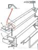
The drawing below shows all the fasteners that will need to be installed on the posts and base to secure the movable section.

1. Guide beam; 2. Roller supports or trolleys; 3. Removable end roller; 4. Lower catcher; 5. Upper catcher; 6. Upper clamp with rollers; 7. Plate for fixing roller supports
It is necessary to install a channel on the made foundation of the base, and then on the pillars or wall (depending on the design) a trolley and fixing brackets with rollers. The gate section will move along them in the future.

On the other side of the structure we mount a section catcher and an end roller.
The sequence of work and components may vary depending on the chosen scheme!
Sliding gates require a metal section that opens and closes the entrance/exit to the site. It and the frame are welded exactly to size; the correct operation of the device depends on this. An example and section diagram is shown above.
The manufactured section must be sheathed with suitable materials. They should be light, practical, and functional. Sheets of metal, stainless steel, corrugated sheets, and polycarbonate are suitable. The choice is up to the builder.
After this, the structure is sheathed with rivets, bolts, and screws.
Finally, the moving part is mounted on the prepared structure. The fixing brackets are removed and the section is secured to the channel (guide rail). Then the fixing brackets are placed in their original place. The work, in general, is not difficult; it only requires accuracy and precision.

After studying the diagrams and recommendations for installing sliding gates, you need to decide on your own designs and algorithms for installing this structure that meets the parameters and requirements necessary for a particular site.
You can see how to make sliding gates with your own hands from corrugated sheets in the video clip:
Another option:
Most builders who build a sliding gate structure on their own site with their own hands install roller carriages on platforms with welded studs.

“This is, of course, convenient and practical. After all, replacement in the event of a breakdown will be carried out easily and quickly!”: they think. But this is a mistake.
If the installation is done incorrectly, the channel will have to be drilled again, threaded, set to the required size, and so on.
The tiny distance will require several days of repair work and will end with cutting out the stud and welding the carriage to the base of the foundation.
Therefore, you need to follow proven instructions; this will allow you to install this structure in the shortest possible time, saving effort and money.
Yes, sliding gates are not cheap, but with the simplicity and manufacturability of the device, they will give a head start to swing and overhead gates. Installed strictly according to the correct technologies, they are less likely to deform and jam.
Previously, sliding gates were installed only at industrial facilities and enterprises, but over time, the ease of use of such structures has brought them well-deserved popularity in private households. Their mechanism is not as simple as that of conventional gates, so most owners prefer to order production and installation from specialized companies, however, if desired, they can do all the work themselves. You can learn about how to make sliding gates with your own hands, as well as about their varieties, assembly and installation stages from our article.
Forged sliding gates
What is this – a sliding gate?
Let's figure out what sliding gates are, what they are like and what their differences and advantages are. Gates of this type consist of a door leaf mounted on rails made of a metal profile, which smoothly moves along guides using special rollers. The mechanism saves space, is automated and operates thanks to an electric motor with a power of 40-100 W. Depending on the type of fastening, there are sliding gates on a rail, cantilever gates and hinged gates. Let's look at each of the designs in more detail.
Mounted
Such gates are usually installed at the entrance to the territory of industrial enterprises. Their design ensures the movement of the web along the upper beam using roller carts, and the height of the opening allows the passage of freight vehicles. Recently, hanging gates, despite their reliability and long service life, are used less and less due to the significant cost of metal for their construction.

Console
This type of gate does not have an upper beam limiting the opening, and moves on roller blocks along a console, which is located at the top, bottom or in the middle of the door leaf. The bottom-mounted design is easier to implement, since the other two options require the construction of additional supports.
 Gates with a console located in the middle
 Sliding on rail
The sliding design, which moves along the bottom rail on rollers, is reliable, but not very practical. If debris, snow, or ice freezes on the rail, it can temporarily disable the gate. Therefore, if you do not plan to constantly clean the area around the gate or live in an area with a harsh climate (heavy snowfalls, long winters), it is better to choose a cantilever opening mechanism.
 Mechanism with bottom rail
 Choosing material
Making sliding gates with your own hands will require the use of the following materials and components:
- pipes for the frame with a rectangular section 60x30 mm and 40x20 mm;
- sheathing material (corrugated sheet, board, lining, polycarbonate);
- metal or concrete supports;
- U-shaped channel No. 20;
- reinforcing rod with a diameter of 12 mm and concrete mixture;
- electric motor;
- rack;
- set of accessories and fasteners;
- set for electrical wiring (wires, cables, protective pipes).
The material is purchased after drawing up a drawing and calculating the dimensions of the gate. It is not recommended to make fittings yourself; you can buy everything you need in hardware stores and showrooms that deal with door structures.
 Required components
 When choosing, pay attention to the quality of metal guides. They must have the correct shape, smooth edges and a wall thickness of at least 4 mm. Check how the roller moves inside the guide. To avoid problems with opening in the future, it is preferable to take parts with a smooth motion. It is very important that the channel and rack match the length of the door leaf, taking into account the counterweight.
Automation is selected based on the approximate weight of the structure. Also important are the wind loads acting on the gate, which depend on the height of the leaf and the material from which it is made. Taking into account the increased loads due to icing and snow placed on the engine in the winter, it is advisable to purchase models with power reserves. For example, for sliding gates weighing about 400 kg, an electric drive designed for a weight of 800 kg is suitable.
Sliding gate diagram
When drawing up a design drawing, you should correctly calculate the height and length of the gate, as well as the dimensions of the counterweight (the tail part located outside the opening). The height should correspond to the fence, the length should correspond to the width of the opening, the tail should be made approximately half as long as the gate leaf.
 Recommended parameters for sliding gates with an opening of 4 m
 At the same stage, the type of frame is determined. It can consist of a frame and 2-3 sections of rectangular pipes fixed at an angle or a frequent sheathing of horizontal and vertical guides. If desired, such gates can have a built-in gate, but this requires the purchase of additional materials - profiles for the frame, hangers and other fittings. In addition, the threshold of such a gate will be high, and this will create inconvenience for children and the elderly.
We build sliding gates
Since sliding gates with a top suspension and mechanisms moving along a rail are not very convenient for use in private homes, we will consider the stages of construction using the example of a cantilever structure with a bottom fastening. Work begins with an inspection of the site.
It is necessary to make sure that there is free space around the gate for rolling back the canvas, and that the terrain is sufficiently level. If old gates are being replaced, they are inspected, assessing the condition of the supports. It is not necessary to demolish and replace strong pillars with new ones; they can be used for a sliding structure. Next comes the turn of excavation work.
Foundation and guides
The base for the gate is placed along the fence (from the site side) in the direction of its opening. Under the foundation you will need to dig a trench 50 cm wide and 1.5-2 m deep, depending on the level of soil freezing. At the same time, holes are dug for the supports if they could not be preserved from the previous structure.
 Scheme of concreting and installation of guides
 A cushion of carefully compacted sand and gravel is poured onto the bottom of the trench. Then, a frame for the foundation is welded from the reinforcement, and a channel is welded on top of it. This will become the bottom part of the gate to which the motor and roller assemblies will be attached.
The frame is placed inside the pit so that the channel is located close to the support pillars and is flush with the ground surface. To prevent concrete from spreading, formwork made of boards is installed along the edges of the trench. It is advisable to immediately take care of the power supply to the engine and, at the stage of laying the foundation, lay the wiring in protective polyethylene pipes.
The trench is concreted with a mixture of cement, sand and crushed stone in a ratio of 1:2:4, water is added depending on the moisture content of the sand, until a creamy consistency is formed. It is recommended to use a concrete mixer for mixing.
 Foundation formwork
 The finished solution is poured into the pit gradually, trying not to disturb the position of the reinforcing frame. After pouring, the foundation is pierced in several places with a reinforcement rod to allow excess air to escape. It takes about a month for the base to completely harden, but you can begin further installation work within a week.
Installing gate posts
The installation of sliding gates does not require the use of powerful supports; usually metal or concrete pillars with a diameter of 10 cm are sufficient. They are installed at a distance equal to the opening, buried at least 1 m into the ground, leveled and filled with concrete. It is better to do this simultaneously with preparing the trench for the foundation.
Along with metal ones, brick supports are also popular. To construct them, a pipe or channel is installed in the center of the planned pillar using the method described above and pieces of reinforcement (mortgages) are welded to it in the places where the components of the gate mechanism will be located. Then, the support is covered with brick so that the reinforcement remains outside. Subsequently, structural parts are attached to it.
 Structure of a brick support
 Fastening the main elements
When assembling a sliding gate structure with your own hands, first connect all the mechanical parts, and then connect the electrical ones. First of all, roller carriages are attached to the mortgages, along which the web moves. On the opposite post, at the top, and sometimes at the bottom, so-called traps are welded (lightly at first), ensuring smooth closing of the gate. The installation process will be described in more detail below.
 Location of main elements
 Preparing the moving section
An important stage of work is the construction of the section frame, consisting of a frame and a counterweight. To do this, you will need to select a flat area of sufficient size to accommodate the entire structure.
Previously purchased pipes with a rectangular cross-section are inspected for corrosion and, if necessary, polished. Markings are applied to them and the necessary parts are cut out with a grinder. Then, checking them with the drawing, they are laid out on a flat surface and lightly secured by welding. The resulting structure is checked for dimensional conformity and absence of distortions, and the frame parts are welded together using a continuous seam. Stiffeners are made in the same way. At the bottom of the section, a guide profile and a gear rack are attached.
 Frame construction
 The finished frame is treated with a sanding attachment; it is also recommended to prime and paint it. To do this, the frame is installed vertically and coated with an automotive primer using a sprayer, and after drying, paint is applied in two layers.
Section covering
After waiting for the painted frame to dry, you can move on to the sheathing. Typically, inexpensive and practical corrugated sheeting is used as a cladding material, but it is possible to use boards or polycarbonate. The selected material is attached to the frame with bolts or self-tapping screws every 20-30 cm, after marking it and drilling holes for fasteners.
Section installation
The installation of sliding gates with your own hands is completed by securing the section to the poles and connecting the automation. You can start installing the gate no earlier than a week after concreting the foundation and supports.
Installation sequence:
- Roller carts are welded to the channel laid on the foundation; the rollers are placed inside the guide at the bottom of the web.
- The gate is checked with a building level and its upper part is fixed with a bracket.
- The movement of the gate is checked and, if everything is in order, the roller carriages are firmly welded.
- An end roller is attached to the front of the section from below.
- The gate is closed and the coincidence with the catchers on the support is checked; if necessary, their position is adjusted.
After assembly, the welding areas are treated with an anti-corrosion primer and the electric motor is connected in accordance with the documentation supplied with it. The structure is ready and if you take proper care of it, remembering to periodically clean and lubricate the rollers, it will last for many years.
 Connecting automation - the final stage
 We hope our instructions on how to make sliding gates yourself will be useful to you. But remember, before you start work, you should draw up a draft of the future design and discuss it with a specialist. Good luck!
In this article we will tell you about all the intricacies of construction and installation, as well as all the possible problems that you may encounter if you decide to make sliding gates with your own hands. When faced with the task of installing sliding gates for the first time, the biggest mystery seems to be the drawing of the sliding gate. In fact, the design of sliding gates is very simple, their installation diagram is also not complicated, and below we will describe the basic principles of installing sliding gates, after understanding which you will no longer have any questions about how to install them yourself. But first things first.
Sliding gates. We calculate the optimal opening width
This is the most important question that you must answer for yourself first of all. By the width of sliding gates we mean the width of the gate itself, i.e. free distance between gate posts when the gate is fully open. To answer this question you need to decide on just a few points:
- What kind of cars will enter through these sliding gates? Only cars? Gazelles? Tractors? Kamaz?
- At what angle will all these vehicles, especially trucks, enter?
According to my own feelings, sliding gates should be such a width that when driving through them, between the gate posts and the mirrors there is a gap of no less than 30 cm on each side (or better yet, 50 cm). And now some statistics about the width of some cars (including mirrors).
- Ford Focus 3 = 2.01 m.
- Ford Explorer 2015 = 2.29 m.
- Gazelle (all-metal van) = 2.5 m.
- KamAZ = 2.9 m.
Just don’t say that you have already built everything and no more trucks will ever enter your site. I assure you that in life there will be enough situations in which you will need to allow trucks onto your site. Now let's answer the question: at what angle can such cars approach you? According to statistics, the angle of entry of such vehicles into the site is 45 degrees to the goal line. See for yourself, the length of a typical KamAZ 65111 is 7.34 meters, and now go to the place on your site where you plan to install sliding gates, look at the space behind them and try to answer the question of whether the truck has enough space for to turn around and drive into your sliding gate at right angles to the goal line?
If we were right and the angle of entry of the truck is approximately 45° to the goal line, then according to the Pythagorean theorem, in order for a 2.9-meter wide KamAZ truck to pass into your gate at an angle of 45 degrees WITHOUT ANY GAP between the mirrors and gate posts, the width of the gate should be 4.1 meters. However, we do not recommend relying on this figure because, firstly, it does not take into account the gap, and secondly, there are situations when a car passing through the gate can either sway for some reason or slide to the side on snow or ice or dirt, slip and move to the side, etc. Based on these considerations, we recommend installing sliding gates with an opening width of at least 4.5 meters.
If we move from theory to practice, then our own experience suggests that the optimal gate width is 4.5 meters, and the ideal gate width is 5 meters.
Please note that everything written above concerned the width of the gate opening, but not the width of the gate leaf! If we talk about the door leaf, then there is one important point that needs to be taken into account. The width of the gate leaf should be approximately 20 centimeters greater than the width of the gate opening! Otherwise, when the gate is closed, you will have a gap noticeable at an angle to the plane of the gate (see photo below). If you forgot to ask for a gate leaf to be made a little wider than the planned opening width, you can correct the situation by installing the gate posts a little closer to each other than planned. This way you will reduce the width of the opening by about 15-20 centimeters, but will avoid the formation of a gap.

Sliding gates. Nuances with the height of sliding gates
It may seem to many that this moment is not worth attention or discussion at all, but this is not so. We partly agree. Indeed, ignoring this point will not create any significant problems for you. except aesthetic. Many people believe that if the height of the fence adjacent to the gate is 2 meters, then the height of the gate leaf should be 2 meters. In reality this is not the case. Let's look at an example:
- We have a fence made of corrugated sheet metal, 2 meters high and installed without tape and without a gap at the bottom. In this case, the profiled sheet rises directly from the ground to a height of 2 meters. (we published an article about installing a fence earlier: Fence posts. We build a fence with our own hands without mistakes)
- When ordering or making your own gate leaf frame, you are guided by the same profiled sheet, which has the same height as the fence - 2 meters, right?
Now let's see what happens as a result. In both cases, you are guided by the same height of the profiled sheet, but you do not take into account the fact that in the case of a fence, the profiled sheet starts directly from the ground and its upper edge is located at a height of exactly 2 meters above the ground. Moreover, in the case of gates, the lower edge of the sliding gate cannot touch the ground; it is raised approximately 10 cm from the ground.
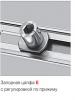
To be fair, it should be noted that the gap between the ground and the bottom of the gate is adjusted using adjustment pads, which are included as standard in the roller kit (see photo on the right and photo below). The roller supports are put on and attached to the adjustment pads using nuts, and with the help of the same nuts, the installation height of the roller supports (and therefore the gate frame) can be adjusted within 5 cm. As a result, the minimum distance from the ground will be 10 cm, the maximum - 15 cm from the ground.
Go ahead. Unlike a fence, a gate profile sheet is usually inserted into the profile that makes up the frame of the gate leaf, and the profile is usually welded from a 60/40 mm rectangular pipe. The height of the gate has already reached: 100mm + 40mm + 2000mm + 40mm = 2180mm. But that’s not all, since a guide beam with a height of 60 mm (for gates weighing up to 350 kg) is welded to the door leaf from below. In total, taking into account the guide beam, the distance from the ground surface to the upper edge of the gate is already 2180 mm + 60 mm = 2240 mm. As you can see, according to calculations, the top edge of the gate was 24 cm higher than the top edge of the fence!
For reference: the sizes of the guide beams that come complete with rollers and other components for sliding gates vary (). Each kit has its own name and is used depending on the size and weight of the gate:
- MICRO set: sliding gates with an opening up to 4 m and weighing up to 300 kg inclusive; dimensions of the MICRO guide beam - height 55mm, width 60mm, thickness 3mm, standard length 4.5m / 5.3m / 6m;
- ECO kit: sliding gates with an opening of up to 5 m and a weight of up to 500 kg inclusive; dimensions of the ECO guide beam - height 60mm, width 70mm, thickness 3.5mm, standard length 5m / 6m / 7m;
- EURO set: sliding gates with an opening up to 6 m and weighing up to 800 kg inclusive; EURO guide beam dimensions - height 75mm, width 90mm, thickness 4.5mm, standard length 6m / 7m / 8m / 9m;
- MAX set: sliding gates with an opening up to 12 m and weighing up to 2000 kg inclusive; dimensions of the MAX guide beam - height 135mm, width 130mm, thickness 5mm, standard length 6m / 9m;
To avoid such an aesthetic mistake, the height of the sliding gate frame should be based not on the height of the filling profiled sheet, but on the height of the fence adjacent to the gate.


Sliding gates. Drawing and diagram of sliding gates.
Sliding gates have such a simple design that you don’t need any drawing of the gate. Below we will explain to you the operating diagram of sliding gates, after which you can easily understand their design, what depends on what in it, what and how you can change in it at your discretion. So, the basis of the entire design of sliding sliding gates is 2 rollers and a guide beam moving along them (sometimes called a “guide rail”). Look at the photo below.


The guide moving along the rollers is the basis of the entire structure. The guide is welded from below to the gate frame and now the entire frame moves along the rollers. Since the rollers should not be in the gate opening, so as not to get in the way, they are moved to the side, outside the gate opening, and the sliding gates are accordingly extended with the so-called “counterweight”. The generally accepted design is one in which the length of the “counterweight” is equal to half the length of the gate opening. In other words, for a gate opening of 5 meters, the total length of the frame will be 5 + 5/2 = 7.5 meters. At the same time, 2.5 meters in this frame will be the same “counterweight”, which extends beyond the gate opening and rests on rollers.
Strictly speaking, it is generally accepted that the length of the gate counterweight is 1/3 - 1/2 the length of the opening. But we strongly recommend making the counterweight 1/2 the length of the gate opening. Why? Because people very often make a “lightweight” counterweight - a triangle (as in the figure below). As a result, not only do they reduce the length of the counterweight to 1/3 of the length of the opening, but they also truncate the “counterweight” to a triangle, thereby reducing its weight. In this case, it simply stops performing the function counterweight- it turns out too easy. As a result, the sliding gates will be “out of balance”, “peck” when closing and when fully opened, and all the loads fall on the rollers, which, as a result, fly out in 2-3 years, and not in 10 years, as they should . Bottom line: if the counterweight is “square”, then, in principle, 1/3 of the opening is enough. If “triangular” - then 1/2 of the opening. But the ideal option would still be the length of the counterweight equal to 1/2 the length of the gate opening.
That is why the basis for installing gates is the installation of rollers. It is the rollers that hold the entire structure and experience the greatest loads in comparison with all other structural elements of sliding sliding gates. These two rollers hold the entire gate leaf hanging over, so they are installed on a massive reinforced concrete foundation, into which, for convenience, a embedded part made of a channel is poured. This is done to simplify the subsequent installation of the rollers, and it is to this that the bases of the two rollers are subsequently welded, and even later - the base for attaching the motor of the recoil mechanism. (see photo above).
All other components for sliding gates carry virtually no force loads and serve to keep the gate leaf from swinging. All these components for sliding gates are shown below. Of these, the support rail (a square bracket with two rubber rollers), the lower catcher and the upper catcher are mounted on poles.

Let's look at the entire set of components needed to install sliding gates element by element. Look at the diagram below, where we have numbered all the elements. So, element by element according to the numbering in the diagram:

- End cap for the rear of the guide. Its purpose is partly decorative, partly to prevent snow from getting inside the guide when the gate is rolled back in the winter if they roll back, raking the snow;
- Support rail with two adjustable casters (square bracket with two rubber casters). It is installed in the upper part of the post (closest to the mortgage with supporting rollers) and simply holds the gate leaf in a vertical position from swinging and tipping over;
- Upper catcher. It is installed on the “receiving” pole. The role of the catcher is to keep the gate leaf from swinging when the sliding gate is closed;
- Bottom catcher. Almost the same as in the previous paragraph, but with a support platform onto which the support roller rolls when the sliding gate is completely closed. The point is not only to keep the sliding gate from swinging, but also to relieve the load on the drive rollers and guide, which experience strong bending loads when the gate is fully extended;
- Support roller. This roller is both a damper and a plug for the front edge of the guide. When closing the gate, it rolls into the “lower catcher” (see previous point No. 4), dampens the impact of the closing gate leaf, rests with its roller on the support platform of the “lower catcher”, removing bending loads from the guide and the entire gate leaf;
- Actually, the guide itself (or “guide rail”), thanks to which the sliding gate moves back and forth along the rollers (rollers on the sliding gate diagram under No. 7). As we have already written above, the guide is plugged on the rear side by element No. 1, and on the front side by element No. 5.
- Support rollers with adjustable supports are elements that bear the main load and ensure rolling of sliding gates. In fact, these are the most powerful structural elements that require fastening to a solid foundation in the form of a mortgage, usually mounted on a reinforced concrete foundation.
Adjustment stands are used for:
- precise alignment of the roller bearings along one straight line (if the rollers are not aligned in a straight line, they will wear out greatly. Without adjusting stands, the rollers are almost impossible to align exactly)
- adjusting the height of the gate relative to the ground (within 5 cm)
- the possibility of replacing worn-out roller bearings (if the roller bearings were welded to the mortgage without adjusting supports, then it would be problematic to replace them without the use of a welding machine “grinder”).
We install sliding gates. Mortgage, foundation, pillars.
For many, the embedded element raises many questions, since the shape and dimensions of this embedded part are unclear and everyone begins to look for its drawing. You don't need a drawing. The point of this element is only to prepare a kind of foundation on a concrete base for the subsequent installation of rollers and a gate drive using electric welding. Based on this, the shape does not matter at all, the dimensions can vary. Channels No. 10, 12, 14, 16, 20 are used as a mortgage. The more massive the sliding gate, the more powerful the channel. The mortgage should stand directly on the line of movement of the future gate leaf, the platform for the engine is shifted from this line into the yard.

Look at the photo below. As you can see, rollers are mounted on the embedded element (in the photo they are numbered 1 and 2). From the same photo it is clear that it would be more logical to move roller No. 2 to the right, closer to the right edge of the gate frame (the attachment point is determined when the gate is completely closed).
It would seem that ideally, roller No. 1 should stand at the very post (which is located in the photo on the left), and roller No. 2 should melt at the very edge of the guide rail, closer to the edge of the gate frame (in the photo on the right). This is almost true, but there is one caveat! The fact is that the guide beam has elements inserted inside at the edges. The edge of the beam farthest from the gate opening is closed with an end cap (number 4 in the photo), and an auxiliary support roller is inserted into the opposite edge (number 3 in the photo), which rolls into the lower catcher when the gate is closed. Therefore, rollers No. 1 and No. 2 must be installed at appropriate distances. The length of the embedded element can be equal to the length of the “counterweight” of the gate. That is, with a gate opening width of 5 meters and a “counterweight” width of 2.5 meters, the length of the mortgage can be approximately 2.3 - 2.5 meters. To install a drive with an electric motor in the future, weld a pad to the embedded element anywhere. On the other hand, you can not do this and subsequently weld a plate protruding to the side to the embedment on top and install the drive on it.

Now about the foundation. The foundation of sliding gates is perhaps the most important and critical part of the entire gate structure. First of all, a foundation is needed for a mortgage to which the main support rollers will be attached. Some companies and private teams offer a cheaper foundation option than reinforced concrete, namely, they suggest screwing in several screw piles, onto which a mortgage is then welded on top and almost everything is ready. Next, next to this bunch of piles, another one is screwed a little crookedly (since it is impossible to screw a whole bunch of piles exactly next to each other), under the post. We will not even consider this option. Perhaps it is suitable for small and light sliding sliding gates, for example, having a length of 3 meters with a light frame sheathed with corrugated sheets on one side, however, longer and heavier sliding gates will “walk” on such a foundation.
We believe that there is no alternative to a reinforced concrete foundation in this case, however, it can be poured in different ways. So, for example, on the Internet it is often proposed to pour either only one foundation - directly under the mortgage, or two separate ones, one of which is under the mortgage, the second - under the “receiving” pillar. This option is shown in the diagram below.

This option is much better than the idea of using screw piles, however, having two separate foundations can end up in trouble, especially in cases where such foundations are not buried below the ground freezing level. The fact is that as a result of frost heaving, such separate foundations can move independently of each other. In this case, even with slight displacements relative to each other, everything may end up in the fact that the sliding gates will no longer fall into the catchers installed on the receiving post and you will have to constantly try to reconfigure the catchers. What if such deformations occur twice a year, for example at the beginning and end of winter? What if even more often? Do you want to devote your whole life to the eternal adjustment of gates on your site and become a guru in this matter? Personally, we don’t!
The solution to this problem is quite simple (but more expensive than two separate foundations) - both pillars must be connected by one common foundation. In this option, even in cases of displacement of the foundation, both pillars will ALWAYS be parallel to each other, moving in one bundle. Below we publish a photo of such a sliding gate foundation.


Sliding gate posts are installed before the foundation is poured with concrete. In the case of sliding gates, the pillars bear virtually no load other than wind. This means that the gate leaf usually has a high windage and during strong winds, the wind load is transferred from the gate leaf to the posts. If we talk about sufficiency, then for such gates it will be enough to take a 60x60x2mm pipe, however, for those who suffer from gigantomania just like us, we recommend making pillars from a 100x100x4mm pipe.
As to whether it is worth installing “U”-shaped pillars or regular ones, there is no consensus. The components for sliding gates described above can be installed on single posts without any problems. We prefer "U" shaped posts, but if you look closely at the photos in this article, you will see that we originally installed and poured single posts with concrete. At the same time, installing small embedded steel plates in the lower part, to which other pillars of a smaller cross-section than the main ones were subsequently welded. Thus, we made “U”-shaped ones from single pillars. “U”-shaped posts are preferable if you subsequently plan to install not only a gate drive, but also one that includes photocells. Firstly, it will be more convenient to install photocells on internal poles, and not on external ones (for anti-vandal reasons). Secondly, inside the internal pillars it will be convenient to conduct hidden wiring to the photocells and signal lamp. You can read more about this in our article "".
Sliding gates. Gate frame design.
It is better to weld the frame of sliding gates from metal. Structurally, it is welded from rectangular or square pipes of two sizes. Pipes of a larger cross-section are used as a load-bearing frame; the internal filling in the form of stiffeners is made from pipes of a smaller cross-section, for example 20 x 20 mm.
We suggest you choose the cross-section of pipes for the sliding gate frame depending on the weight and/or length of the gate, according to the tables presented below:
- Light gate lining (corrugated sheet, polycarbonate, mesh, Euro picket fence):
- Heavy gate lining (board, forged elements, metal square, etc.):


It is better to immediately weld the gear rack to the frame (or cylinders with threads for fastening the gear rack). Gear rack fasteners (threaded cylinders, 3 pieces per 1 meter of rack) come standard with it. Be sure to check this fact when purchasing! So that the automation can be installed later without any problems. Otherwise, it will be extremely inconvenient to weld it exactly to the very bottom of the gate. Its length should be at least 1 meter longer than the length of the opening. This extra 1 meter (or more) of the toothed rack protrudes onto the “counterweight” of the gate in order to always be in mesh with the gear of the gate drive motor. The rack is universal and fits 99% of drives (CAME, NICE, Dorhan, Alutech, etc.). If you are welding cylinders with threads for subsequent fastening of the gear rack, then it is better to weld them to the guide (guide rail) in advance, as shown in the two photos below.


Now pay attention to the photo of the sliding gate below. In this photo it is visually clear how strong the loads are on the rollers that actually hold the sliding gates and on which these gates roll. Keep in mind that if you decide to make a gate in a sliding gate (by cutting it directly into the gate leaf), then it should be done in that part of the gate that is located closest to the supporting rollers on which the sliding gate is held. If you decide to install a gate at the end of the door leaf farthest from the rollers, then you will further upset the balance of weight distribution, “increase the leverage” and the forces acting on the rollers.

Accessories for sliding gates
If we talk about components for gates, we would recommend components from the ROLTEK brand because they have proven themselves to be the most reliable ones offered on the market today. Gate components are usually kits, the same as in the photographs and diagrams in our article (above the text). These sets of components are divided by power, depending on the length and weight of the door leaf. You will find the best prices for components for sliding gates on our website in the “Discount Price Store” section => “”. Components for ROLTEK gates are divided as follows, as indicated in the table below:
You might also be interested in:
- We order a sliding gate frame. What you need to consider before ordering This article will tell you what you need to know before ordering... Automation for sliding gates is not only the gate drive itself, which directly opens and closes the gate leaf. Drive unit...
- Wicket in the gate? All pros and cons. If we try to list all the arguments in favor of making a gate embedded directly into the gate...
- If you want, you can change almost any of the objects around us beyond recognition. Everything is limited only by our imagination. Imagine... Do-it-yourself fence. If you decide to build a fence with your own hands, then most likely the rationale behind self-construction is to save money or...
– an ideal option for fencing structures, a country house or a building with seasonal residence. But it is not always possible to order a product from the manufacturer and then you have to assemble it yourself.
Advantages of homemade simple sliding gates
The advantages of self-installation of such a structure include:
- The ability to make simple ones of almost any width, having provided in advance the features of your site. It often happens that in the spring, when the soil thaws and begins to heave, the structure warps. For this reason, gates are usually made no more than 4 meters wide with two leaves to avoid unnecessary deformation. If you need a canvas, for example, 7 meters wide, then you pre-concrete the pillars and make the structure resistant to weather changes. This span allows large equipment to enter the site.
- A budget option. For those who do not want to install gates with two leaves, and ordering ready-made sliding ones is expensive (the cost of the electromechanical gate mechanism alone is more than 50 thousand), it is quite possible to assemble the structure yourself.
- Low probability of breakdown. The absence allows you to avoid unexpected breakdowns and make repairs cheaper.
Main constituent elements
Consider a 7 meter wide gate with a wicket and a homemade lock. Such gates can easily open to any width - 5, 6 or 7 meters.
To prevent such a large canvas from moving, it is better to make a lintel on top of the gate.
The movable mechanism is made of ordinary furniture wheels made of hard plastic. They move along a rail, the depth of the hole for it is 25 cm.
To prevent the 7-meter sliding gate leaf from swaying in the wind, we make a pin in the middle that rests on the frame or the ground.
It is advisable to make the gate itself according to the principle of a rod system (“truss”, used in the construction of railway bridges). Enough to strengthen the structure of a pipe with a cross-section of 40*40 mm, the main pillars are suitable for 60*40 mm, the jumper logs are made from a 20*40 pipe. It is also recommended to scald the perimeter with a 40*40 pipe. The stiffening angles can be welded from the remains of the pipe.
When welding a wide structure, it is necessary to create a level working surface, for example, using a boardwalk.
Installation of gates and reinforcing frames
On the right side, you can fasten it close to the posts using a tack at the top and bottom. But then there must be an indentation on the left that allows the canvas to move freely without touching other elements. 4 cm is enough.
When preparing a hole, it is necessary to remove 40 cm of soil, fill it with crushed stone, ASG, and pour concrete to the depth of a bayonet shovel. Concreting of the ditch is carried out from pillar to pillar. A corner is pressed into the still weak concrete.
Video: DIY sliding gates
The problem of limited space is relevant not only for urban but also for suburban life. It can occur already at the entrance to the territory of your personal plot. At the same time, very often, the problem is aggravated by the presence of swing gates, which require a lot of free space to open. The situation is completely different with sliding structures, which almost always successfully solve a similar problem. From this article you will learn how to make sliding gates with your own hands and what is their main advantage over the traditional type of entrance gate.
Main features of sliding gates
Sliding gates are a modern and practical design that allows you to save a lot of free space required to open them. The peculiarity is that the gate leaf moves along the fence, while occupying a minimum of space. This is the main advantage of sliding gates over swing gates.
Modern classification involves dividing sliding gates into varieties according to the following criteria:
Degree of automation of gate opening and closing
Based on this parameter, two types of structures are distinguished:
- Mechanical;
- Automatic.
Mechanical sliding gates are the cheapest and simplest option. Opening as well as closing of such structures is carried out only manually.
Automatic sliding gates have much wider functionality than their mechanical counterparts. The person is only involved in pressing buttons.

Despite the fact that gates with an automatic opening mechanism are much more expensive than regular ones, they are one of the most popular types of designs today.
Interesting to know! The price of automatic gates depends not only on the features of the opening mechanism, but also on the type of automation used.
Automation for sliding gates
The door leaf moves using an electric drive, which can be started in the following ways:
Start button
The device is turned on by pressing the corresponding button. The disadvantage of this method is that the button is located directly next to the gate.

Remote control (RC)
This is a much more convenient option than the push-button method. The remote control allows you to open the gate from a distance. In this case, it should be located directly in front of the receiver. To stop the blade, limit switches are provided.

GSM module
It represents the most advanced way to control sliding gates. Distance here does not matter at all, and you can give a command to open or close structures from another country or even continent. The main thing is that the areas are provided with high-quality mobile GSM communications.

Construction and design of sliding gates
According to this criterion, sliding sliding gates are divided into three types:
- Rail;
- Hanging;
- Console.
- Rail gates- are the easiest option to manufacture. The shield together with the frame moves by means of rollers along a special guide rail fixed to the base. This type of construction can be used on various openings, but the most popular is the opening - the minimum width and height of which is 7 m and 2.4 m (respectively).
Gates on rails are not limited in terms of the location of the drive, placing the least load on it. However, rails of such designs require additional maintenance, especially in winter.

- Hanging gates- are very similar to their rail counterparts, except that the guide rail is placed in the upper part of the structure, and the shield together with the frame is suspended from it by means of rollers. Thus, such structures set certain restrictions on the height of passing vehicles, which depends on the level of the guide rail.
The drive mechanism is also located at the top, which significantly complicates the work associated with the repair and maintenance of equipment.
Installation of hanging sliding gates is most in demand on sloping areas and in openings of non-standard size.

- Console gates- do not have any restrictions in terms of the height of the opening. There is also no need to arrange a foundation along the length of the structure, this is explained by the absence of a guide rail.
The big disadvantage of cantilever-type gates is the need to install a reinforced support column, which supports the weight of the entire structure, as well as the presence of additional space for a counterweight and console. The standard console is in demand in openings with a height and width of 2.4 m and 6 m (respectively).

Number of sliding sashes
There are two types of sliding gates:
- Single leaf;
- Bivalve.
The second option, in addition to the additional sash, requires the installation of an additional drive mechanism, which leads to a significant increase in the cost of the structure. That is why the demand for double-leaf sliding gates is less than for single-leaf ones.

DIY sliding gates (drawings, diagrams)
If you decide to install sliding gates with your own hands, do not forget that the convenient and long-term operation of structures is determined by a number of factors that must be taken into account.
To make a door leaf for a sliding gate, you will need a set of plumbing tools, which include:
- welding machine;
- carpentry clamps;
- grinder with cutting and grinding discs;
- measuring tape or tape measure 7 m long;
- chalk or pencil;
It is important to consider that the finished metal structure should not have any bends or distortions, so a perfectly flat area should be used for welding it.

Sliding gate structure (diagram): 1 - Supporting bracket, 2 - steel frame, 3 - lower catcher, 4.5 - supporting carriages (rollers), 6 - electric drive
Fabrication and assembly of the frame
As an example, consider the production of a classic sliding gate design with a counterweight, where the width of the entrance opening is 4 meters.
- To make reliable and durable sliding gates that will serve you for decades, choose steel pipes with a wall thickness of at least 2 mm. The best option is a pipe with a rectangular cross-section 60×40.
Welding work
- Cut the side gate posts to size and lay them on the ground. Place the top and bottom strips between them so that you get an even rectangle. Please note that the bottom bar of the gate must be longer than the top, since the slope will be attached to it.
- So that the internal corners of the frame are straight and have ∠90°, check both diagonals, they should have the same length. This way you will be able to avoid distortion of the structure.
- Tack each corner with a welding point and check the diagonals again. If nothing has changed, you can proceed with the final welding of the frame.

1.3 - upper and lower bars, 2.5 - side posts, 4 - guide rail, 6 - oblique support
Concrete works
Sliding gates are a rather heavy structure and to prevent them from sagging, a reliable base should be installed under the retaining element on which it will rest well.
Such a base is made from a metal channel 20 cm wide and a reinforced U-shaped frame.

- Using reinforcement with a diameter of 8-10 mm, a special hook and knitting wire, a frame resembling the Russian letter “P” is made;
- A channel is welded on top of the frame;
- The finished structure is lowered into a pit and concreted so that its upper part protrudes 5-10 cm above ground level.

Important! Before using the laying pad for its intended purpose, the concrete must be allowed to dry for at least 2 weeks.
Locksmith work
The most difficult stages of the work are over; all that remains is to attach the pipes to the posts and install the gate leaf on the roller supports.
- First of all, roller carriages are welded to the channel along which the guide beam will run;
- Then pipes are attached to the support pillars: a single 60x40, and a U-shaped profile welded from pipes of the same size;
- Next, catchers are welded to the top and bottom of the single pipe, and support rollers are welded to the U-shaped profile;
All welding and plumbing work can be carried out independently only if you have relevant experience in this matter, otherwise it is better to contact qualified workers who can provide guarantees for the work performed.


- The end roller is inserted into the guide beam and securely secured with bolts. It works in tandem with the lower catcher and must fit into it accurately when the gate is closed.
- All that remains is to lubricate all the mechanisms and install the gate leaf in place. If everything is done correctly, the gate should open and close smoothly and easily, without vibration or any jerking.
Important! Over time, the gate leaf may sag a little, so it is advisable to weld the lower catcher a couple of millimeters below the level of the end roller.


Automation and accessories
If desired, the process of operating sliding gates can be made even more functional and convenient if you use automated rather than manual control.
When choosing automation, you should pay attention to the following parameters:
- Weight and type of sash design;
- Conditions and frequency of operation of the gate;
- Operating temperature range and engine power.
If the leaf weight exceeds 400 kg and the gate is planned to be used in winter, it is better to use an industrial motor with a large power reserve, since the load increases greatly at low temperatures.

It is better to entrust the installation and connection of the electric drive to qualified specialists, although it is known from experience that many cope with this task on their own.
As for gate fittings, the service life of the entire structure will directly depend on its quality. You can purchase the necessary kit at any specialized store. Most importantly, do not forget to check with the seller about the availability of a certificate for the product.

Set of fittings for sliding gates: 1 - upper catcher, 2 - supporting element, 3 - toothed lower bar, 4 - lower catcher, 5 - end roller, 6 - guide beam, 7 - roller support, 8 - rollers, 9 - electric drive
Conclusion from what you read
If we take into account all the pros and cons of sliding gates, we can come to the conclusion that there are still more advantages. With its reliability and practicality, this type of fencing has long won the trust of professionals; moreover, this design will look modern and take up little space.