Adjusting the photo relay fr 601. Connecting the photo relay - step-by-step instructions with a video tutorial. Light sensor circuits
It is convenient to control the lighting on the street with the help of a photorelay. The device is practical and has a simple connection diagram. In this case, street lighting fixtures will operate in the required mode.
Photo relay and its operating principle
An effective device allows you to control energy costs and control lighting according to the required mode. Photo relays are used to timely turn on and off street lights, which is important for private homes. For this purpose, the device has a light-sensitive sensor. The element is connected to the food chain. When light rays hit the sensor, it becomes an insulator, and in the dark, the device conducts electricity to the lighting device. This is how a photo relay works, turning off the lights in daylight and turning them on in the absence of sunlight.
Lighting: use of photo relay
The lighting control device is used in private homes, placed on lanterns along paths or near the front door. In a park, large suburban area and other spacious areas, photo relays are also used. The device is practical for lighting parking lots, courtyards, advertising structures and the visibility area of outdoor surveillance cameras. In all cases, an automated system is created that turns on the light when darkness falls. This allows you to save energy resources and ensure comfort in the desired areas.
Characteristics of photo relay
When choosing a device for lighting control, its characteristics are taken into account. Manufacturers produce a wide range of devices that differ in appearance, characteristics, rated supply voltage and other parameters. Therefore, when choosing, you should pay attention to the following features of the photo relay:
- weight and dimensions of the device;
- temperature restrictions during operation;
- response sector;
- power and energy consumption level;
- network frequency for operation;
- rated voltage for supply.
Devices are also divided according to the type of switched lamps. Simple models are often designed to work with conventional incandescent or halogen lamps. For other lamp options, you should choose a photo relay whose power and characteristics correspond to the parameters of the light source.
Types of devices
Photo relays are widely used in various fields and, depending on this, devices are divided into several types. For private use, a photo relay with a built-in photocell is convenient. They are a single block that is fixed on the street. Models that have a built-in photocell and timer are also reliable and more functional. In this case, it is possible to control the lighting according to a given time mode.
Practical devices may have the ability to control the response threshold. Models with a remote element for lighting control are easy to operate. These types are the main ones, but there are also options designed to work in harsh and difficult conditions, for example, in the north.
Devices that include a motion/presence sensor can save energy. The photo relay turns on the light when an object approaches, and if there is no movement for a long time, the lighting turns off.
Manufacturers
High-quality light sensors are produced by manufacturers in many countries around the world. When choosing, it is worth considering that the devices differ in rated supply voltage. Optimum devices that are connected to the network at 220 V.
The main brands are:
- "Frontier";
- HOROZ;
- Theben.
The cost of devices is determined by the type of sensitive element that is included in the design. It is this part that is the most valuable and ensures the high-quality operation of the device. The cost of products is also influenced by the dimensions, characteristics and brand of the manufacturer.
Photorelay IEK FR-601, 602, 606, 603: comparison and features
The manufacturer IEK produces a wide range of light sensors, which differ in appearance, characteristics and other parameters. It is easy to compare popular models using the data given in the table.
| Photo relay type | Peculiarities |
| FR-601 | For operation in single-phase AC electrical networks with a voltage of 230 V and a frequency of 50 Hz and according to the characteristics corresponds to GOST R 51324.2.1. Protection against dust and moisture, maximum load and power lamps 2200 W, operating temperature conditions from –25 to +40 °C, protection degree IP 44, |
| FR-602 | For operation in single-phase AC electrical networks with a voltage of 230 V and a frequency of 50 Hz, complies with GOST R 51324.2.1. Max. lamp load and power 4400 W, operating temperature range from -25 to +40 °С. degree of protection IP 44. |
| FR-603 | To automatically turn on/off light sources. There is a built-in photocell, and the load-switching part is presented in the form of an electromechanical relay. Protection IP44, input voltage 220 - 240 V. |
| FR-606 | For automatic control of street lighting depending on natural light levels. Plastic case, electromechanical relay, operating temperature from - 40 to + 50, voltage 220~240 V. Sensors can be used and timers. |
Photo relay models differ in shape and appearance. These four options are optimal for controlling outdoor lighting and have a simple connection diagram. Devices are installed outside, but there are also models for mounting inside. In this case, only the sensor is located on the street.
How to connect a device to a street lamp: diagrams and principles
When connecting a simple device, you need to familiarize yourself with its design. The main element is a photodiode, which can be located outside or inside the housing. In the first case, the sensor is mounted outdoors, and the electronic unit is connected to an electrical panel indoors. If the sensitive part is located internally, the device is mounted outdoors.
Knowing the design features of the device allows you to connect it to the flashlight as efficiently as possible. Therefore, it is important to determine the type of photo relay, purchase a high-quality device, select a circuit, and then begin connecting the sensor.
Photo relay on the diagram
The correct connection diagram greatly facilitates self-installation of the device. In the electrical diagram, the photodiode is presented in the form of a conventional graphic symbol, which is a triangle on the axis of symmetry with arrows directed from top to bottom. On simple diagrams, the device can be designated as a circle or rectangle with the inscription “FR”.
Connection
The bracket with the device is mounted in a shaded place. Tree foliage, canopies, and precipitation should not affect the operation of the device. After determining the location, you need to find out the number of lamps for which control is required. One photo relay is mounted per light source. If you use a large number of flashlights, then it is best to use a controller. It receives a signal from a photosensor and allows you to control several lamps simultaneously.
The design of the device may include terminals, which simplifies connection. They are necessary for clamping wires. The cable of each color is connected to the corresponding wire of the lamp and power circuit. If there are no terminals, then a junction box should be installed. The device body must be protected from moisture and precipitation. Well-known manufacturers indicate on the packaging or in the instructions the connection diagram of the element.
DIY assembly and connection of a photo relay
It’s easy to create a simple device for controlling lighting with your own hands. Depending on the required level of functionality and skills, both simple and complex circuits can be used. In any case, you need to use high-quality parts and provide protection for the element from climatic influences.
Components
For assembly you need to prepare all the necessary parts. A simple version of the photo relay includes components such as:
- photoresistor;
- device Q6004LT;
- regular type resistor.
The connection and connection diagram of the device is simple and includes a minimum of parts. In this case, the device receives power from a 220 V network, and the principle of operation is to gradually increase the voltage amplitude to 40 V. When this mark is reached, the photo relay is activated and the light comes on.
Scheme
Assembling a simple light sensor involves determining the power level and characteristics of the device. First draw up a diagram of connections and connections to the lamp. To use one photo relay for several lamps, you need to use a controller.
Assembly and installation
This circuit does not include a power supply, making the assembly process simple. The power level can be increased by using a device with higher performance. All components are connected using a cable, and a 40 kOhm resistor is used for adjustment.
The use of a powerful Q6004LT device makes it possible to connect a load with a power of up to 500 W to the assembled device. And the use of an additional radiator in the circuit will increase the power to 750 W. In the future, you can use a quadrac, which will have operating currents of 6, 8, 10 or 15 A.
Lighting operation
When operating a lighting system that contains a photo relay, it is important to ensure the reliability of the device housing. Otherwise, precipitation will render the device unusable, and lighting control will be impossible. Therefore, it is important to choose high-quality photo relays with a reliable housing that protect electrical elements from climatic influences.
When installing, be sure to follow the rules for working with electrical appliances. This helps avoid injury. As a result, it is easy to create a reliable and economical outdoor lighting system.
To adjust the light sensor, use a special regulator located at the bottom of the device. The middle position is optimal, but efficiency can be increased. The setting depends on personal preference. For example, at the maximum value, the photo relay will work at the beginning of sunset and the light will turn on.
Photo relay malfunctions and their elimination
A correctly selected sensor will provide comfortable lighting control, but sometimes malfunctions occur. One of the most common situations is when the street lights turn on during the daytime. A possible reason is that some objects interfere with sunlight, either creating a shadow or providing a stream of light.
For correct operation, the sensor must be installed above the lighting device. The light from the flashlight should not shine on the device body. Water getting inside the sensor can cause a variety of problems, for example, breakdown or blinking of the element. In this case, you need to replace the device with a new one, but be sure to take into account the reliability and tightness of the case and select the location.
Advantages and disadvantages
The photo relay is practical for various objects requiring lighting control. The device allows you to save energy costs by turning off the lamps at the right time. This is the main advantage of the element. It is also worth considering easy installation, the ability to connect several lights to one sensor and simple operation. The presence of a timer and motion sensor makes the device more functional. During use, the sensor does not require constant attention. To get all the benefits, it is important to install the photo relay correctly and choose a high-quality element.
A photo relay is an element of an outdoor lighting electrical circuit. Therefore, correct installation is required when connecting. Otherwise, malfunctions, breakdowns and malfunctions will occur, which will lead to additional costs. And it is also important to choose a photosensor that matches the characteristics of the lamps and the required level of functionality.
Video: principle of selection and operation of photo relay
Lighting control using a photo relay is an effective way to reduce energy costs for illuminating a street or other objects. The sensor, whose parameters match the needs, is easy to install and has a number of advantages. And knowing the principle of operation of the device will allow you to make the right choice.
Every evening you have to turn it on, and every morning you have to turn it off. And if in good weather you can somehow put up with this, then in rain or snow... Therefore, the idea arises to automate the switching on and off of lamps. This is what the photorelay for street lighting does.
There are many names for this device. In the literature you will find the name light-control switch or light-sensitive machine, and when communicating you can hear it as an illumination or light sensor, photosensor, twilight/twilight sensor or day/night. Perhaps there are others. But all this is about one device that turns on the lighting at dusk and turns it off at dawn.
Photo relays are made on the basis of a photoresistor or phototransistor, which change their parameters when the illumination changes. As long as enough light falls on them, the power circuit remains open. As darkness falls, the parameters of the photoresistor/transistor change and, at a certain value (set by settings), the circuit closes. In the morning, the process is exactly the opposite: when the illumination reaches a certain level, the power circuit is broken.
Specifications
First of all, you need to decide whether you want a photo relay for street lighting with an external or built-in light sensor. The remote sensor is small in size and is easier to protect from illumination; the device itself can be placed in the house, for example, in a panel. There are even models for din-rail. A photo relay with a built-in light sensor can be placed near the lamp. It is only important to choose a place so that the light from the lamp does not affect the photosensor. This option is more convenient, for example, for .

Performance characteristics
Having decided on the type of sensor, we move on to the technical parameters:

To select a photo relay for street lighting, these characteristics are required. Their correct choice determines the performance of the device. But there are still some parameters that affect the correct operation of the device.
Customization options
There are several adjustments that allow you to customize the operation of the photo relay in each specific case. The problem is that the settings are made manually by turning the desired knob, and it is impossible to achieve absolutely identical parameters for several devices. There are always some differences in their work.

Using these settings, you can make the operation of the photo relay to automatically turn on the lighting of the area comfortable and eliminate false alarms.
Where to put
Choosing the right place to install a photo relay for street lighting is quite a quest. Several requirements must be taken into account:

With all this, the installation height of the photo relay is at the level of 1.8-2 m. This will make it possible to adjust the parameters “from the ground”. You can go higher, but you will need a stepladder/ladder or a chair/stool.
As you can imagine, finding such a place is not easy. There are several tricks that make the solution easier:

And another piece of advice from practice: it’s easier to adjust the operating parameters if the light sensor of the photo relay is located on the eastern or western wall. But only if there are no brightly glowing objects there. In this case, it is best to choose the side where the “exposure” is least.
Types of photo relay
As already mentioned, there is a photo relay with a built-in and remote light sensor. In addition, you can find the following varieties:

If you need one of the functions described above, it is not at all necessary to buy a photo relay with a motion sensor or timer. You can install a regular sensor and, in series with it, connect the desired device (motion sensor or timer). The functions will be the same, and repairs and replacement will cost less. If one of the parts in a photo relay with additional functions fails, you will have to change the device completely, and this option costs more than its “no frills” counterpart.
Connection diagrams for photo relays for street lighting
The purpose of a photo relay for street lighting is to supply power at nightfall and turn it off at dawn. That is, it is a kind of switch, only instead of a key there is a photosensitive element installed in it. Therefore, its connection diagram is similar: a phase is supplied to the photo relay, removed from its outputs and supplied to lamps or a group of lamps.

The simplest case is a diagram for connecting a photo relay to a lantern
Since the photo relay also requires power to operate, a zero is applied to the corresponding contacts; it is advisable to also connect the ground.
As we said earlier, you need to select a photo relay based on the power of the connected load. But one pattern is observed: with increasing power, prices increase significantly. To save money, you can supply power not through a photo relay, but through. It is designed for frequent power on/off, and can also be used to connect power using a light-sensitive element with a small connected load. In fact, it only turns on the magnetic starter, so only its power consumption is taken into account. And a powerful load can be connected to the terminals of the magnetic starter.

If, in addition to the day/night sensor, you also need to connect a timer or motion sensor, they are placed in series after the lighting relay. The order in which the movement/timer is set is not important.

If a motion sensor or a timer is not needed, simply remove them from the circuit. She remains functional.
Installation and configuration
For a photo relay with a built-in photo sensor, three wires come out of the housing. They are always connected the same way:
- Red goes to the load - a lantern, light bulbs, lamps.
- The brown or black wire is connected to the phase taken from the panel.
- The neutral from the bus with the “working zero” from the panel is connected to the blue one.

It is also advisable to ground the device by connecting it to the appropriate terminal on the housing. The wire cross-section is selected depending on the power of the connected load.
The relay is configured after it is installed and connected. When twilight sets in, wait until you are in a state where you would like the lighting to turn on. Take a small screwdriver and turn the adjustment wheel until the light comes on.
The procedure for connecting a photo relay with an external sensor is slightly different:
- connect the phase to terminal A1 (L) (at the top of the device);
- set zero to terminal A2 (N);
- from the output (depending on the model, it may be located in the upper part of the housing, then designated L’ or in the lower part of the housing), the phase is supplied to the lighting fixtures.
One of the connection options is in video. A circuit with a magnetic starter is implemented here.
Good day, dear readers of the Electrician's Notes website.
Remember, I already told you that, according to the federal program, we installed entrances and vestibules. In this article I want to tell you about photo relays for street lighting of residential courtyards .
External lighting at entrances, or it is also called visor lighting, is carried out using cantilever lamps of the housing and communal services type with protective glass made of polycarbonate. So, these lamps are controlled using photo relays.
We use a light-control switch type LXP-02 as a photo relay for street lighting. This is what he looks like.


This photo relay can also be used to illuminate roads, parks, summer cottages and gardens.
Technical characteristics of photo relay for street lighting type LXP-02
Photo relay type LXP-02 automatically turns the lighting on and off depending on lighting conditions. Those. as soon as it becomes dark outside, the photo relay turns on the street lighting. And vice versa, as soon as it becomes light outside, the photo relay disconnects the lamp from the network.
This results in significant savings and also increases the service life of the lamps themselves.
Below I will give you its technical characteristics:
- power supply 220 (V) AC voltage
- switched circuit up to 10 (A)
- working light level< 5 — 5о (Люкс)
The level of working illumination is set using the regulator at the bottom of the photo relay. If the regulator is moved to the “+” side, then the photo relay will turn on the lamp even when it is slightly darkened or in cloudy weather, but if the regulator is moved to the “-” side, then the photo relay will operate only when darkness falls.
Usually I leave the regulator in the middle position.

There are 2 more types of LXP type photo relay. These are LXP-01 and LXP-03. They differ from LXP-02 only in the current strength of the switched circuit and the level of operating illumination.
Installation of photo relay type LXP
The photo relay is installed on the wall using a special bracket, which is included in the delivery package. The bracket is attached with a screw to the photo relay itself.

When installing, you must make sure that there are no obstacles that prevent natural daylight from reaching the photo relay. Also, there should be no swinging objects, such as trees, in front of the photo relay.
Photo relay circuit
The connection diagram for a photo relay for street lighting type LXP-02 is shown both on the packaging box and on the product itself.


In total, 3 wires come out of the photo relay: brown, red and blue.

Knowing, it is not difficult to guess their purpose:
- brown wire - phase
- blue wire - zero
- red wire - switching phase (to the lamp)
Knowing the photo relay circuit, we proceed to connecting it. produced in a distribution box installed on the wall.
We use a power of 70 (W) as a load.

Connecting a photo relay for street lighting is carried out as follows.


If we describe this diagram in more detail, it will look like this:

If your house uses a grounding system or, then the circuit is powered by a three-wire cable (phase, neutral, ground). If you are still using electrical wiring with a grounding system, then the circuit will differ only in the absence of a PE conductor.
The video version of this article, as well as by popular demand, at the end of the video I showed a diagram of connecting a photo relay through a contactor:
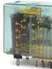
Addendum 1. Due to numerous requests, I posted a photo of the appearance of the printed circuit board of the FR-602 photo relay. I won’t attach the diagram - you can find it on specialized electronics websites.

Addendum 2. Quite often I am asked about the connection diagram for a lamp so that it can be controlled both through a photo relay (in automatic mode) and using a switch (in manual mode at any time of the day). Here I am enclosing a schematic.

P.S. That’s basically all I wanted to tell you about photo relays for street lighting. Currently, this is how we carry out electrical installation of external (canopy) lighting in residential courtyards. If you have any questions, then ask your questions in the comments.
With the onset of evening, the lights along the city streets light up on their own; the automation of this process no longer surprises anyone. Today, photo sensors that control street lighting are available not only to public utilities, but also to ordinary owners of country houses. You can make your home more comfortable and smart without any special financial costs or electrical installation skills; you just need to take into account several important nuances: know the photo relay connection diagram and the rules for working with it.
How light sensor works
The task of the photo relay is to turn on the lighting device when it becomes twilight in the yard and turn it off at dawn. The device is based on a photosensitive element (photodiode, gas discharger, photothyristor, photoresistor), which changes its characteristics in light. For example, in a photoresistor the resistance decreases, current easily passes through this element and closes a contact that turns off the lighting.
Additional elements of the device help to avoid erroneous switching on/off, adjust the sensitivity of the sensor, strengthen the signal from the sensor, etc.
Why do you need a photo relay?
The street lighting system can work without photosensors. But the day-night sensor gives it additional advantages:
- Convenience. A standard lighting system involves installing a switch near the front door on the street, or in the house itself. This is convenient for someone who decides to leave the house late in the evening. But when returning home in the dark, you have to go to the switch with a flashlight, or even open the lock in complete darkness. With the sensor, you can set the backlight to turn on at dusk and the owner will arrive at an already illuminated area at the gate or in front of the garage.
- Energy Saving. Residents of country houses often forget to turn off the lights outside before going to bed or leaving home. This will not happen with a sensor. The standard one will turn off the light with the first rays of the sun, combined with a motion sensor - as soon as everyone leaves the yard, and the programmable one - at exactly the specified time.
- Presence simulation. Thieves do not risk sneaking into a house while the owners are home, and the main sign of their presence is the light being on. Street lighting with a sensor creates the appearance of presence and thus protects the house from vandals and robbers while the family is on vacation or on a business trip.
Light sensors have proven themselves well in urban lighting systems; they are often used by public utilities, owners of shopping centers, parking lots, billboards, etc. In private country houses, photo relays are also beneficial and appropriate, and therefore are becoming increasingly popular.
Selecting a photosensor model taking into account technical characteristics
When purchasing, pay attention to:
- Voltage (volts). Manufacturers produce devices powered by mains voltages of 12V, 24V and 220V. We recommend choosing the latter, as they can be connected to a household network. For other devices, you will have to purchase voltage converters, which will make the designs more expensive and less reliable.
- Switching current (amps). If this setting is not selected correctly, the life of the sensor will be significantly reduced. Therefore, the number of lighting devices connected to the photo relay and the type of lamps used (diode, housekeeper, incandescent) need to be determined before choosing a sensor. To obtain the maximum switching current, you need to divide the sum of the powers of all lamps by 220 (mains voltage). The figure indicated in the device passport must be greater than that obtained as a result of calculations.
- Turn-on threshold (lumens). The parameter determines the sensitivity of the sensor to light. If the sensor is insensitive, the lighting will start to turn on too early, and if the sensor is too sensitive, it will prevent it from turning on in winter due to the reflection of light from the snow. Look in the passport at the threshold adjustment parameters; the range should be 2–100 Lux or 5–100 Lux.
- On/off delay (seconds). The adjustment range is also indicated in the device passport. It should be possible to set a delay of 5-7 seconds so that the lights don't turn off every time a car drives by.
- Power (watts). The lower this indicator, the more economical the device will be. The device passport indicates power consumption in the active phase (up to 5 W) and in standby mode (up to 1 W).
- Degree of protection. Since street lighting sensors are mounted outdoors, drops and moisture vapor should not penetrate into the housing, it should not be deformed due to ultraviolet radiation, etc. The weather resistance of the device must be IP44. If the sensor is placed in a protective box or under a canopy, the figure may decrease. If you select a model with an external photo relay, the degree of protection can be reduced only for the photo sensor, but not for the main unit.
If your region has very harsh winters, pay attention to the operating temperature range, and if there is little space on the facade, give preference to compact models.
Types of light sensors
Conventional inexpensive light sensors allow you to automate lighting and adjust it to the length of daylight hours. But since in this case the light burns all night, manufacturers began to create models with greater capabilities.
Among them:
- Photo relay with motion sensor. They turn on the lights when something starts to move in the controlled area. Thanks to the photo sensor, the switch-on signal is triggered only during the dark period. The device is inexpensive, reliable and compact. But if there are pets running around the area, or there are plant branches in the field of view of the sensor, there is a high probability of a false sensor response.
- Photo relay equipped with both a motion sensor and a timer. The device can be finely tuned so that it only works when needed. For example, from 20.00 to 22.00 when a guest approaches the gate or the owner returns.
- Photo relay with timer. The device makes it possible to save energy by turning off the lights when not in use. If the family’s habits are established and tied to a certain time, this option can be very convenient. Many people prefer this type of device, since they do not have to be installed outside; the timer can give a signal to turn on directly from the house.
- Programmable photo relays. Devices of this type are the most expensive, but superior to other types in functionality. They make it possible to set the lighting on/off depending on natural illumination, time period, day of the week, and season.
The optimal price and functionality are day-night devices with a motion sensor and built-in timers. For the vast majority of everyday tasks, the scenarios they implement are quite sufficient.
Another approach to classifying photosensors is the type of design. There are:
If you have little experience in installing electrical appliances, or you are afraid of damaging the new wallpaper, it is better to prefer an externally mounted photo relay.
Photo relay manufacturers: countries and prices
The production of such devices does not require unique equipment or complex technological processes, therefore, along with Western products, the market offers many domestic photo sensors. Moreover, each country has both budget and inexpensive models with varying degrees of protection.
Comparison table of photo relays from different manufacturers
| Name | Switching current, A | Operating voltage in the network, V | Degree of protection, IP | Manufacturer | price, rub. |
|---|---|---|---|---|---|
| FR-6 | 10 | 240 | 54 | Ukraine | 150 |
| PS-1 | 6 | 220 | 44 | Uzbekistan | 200 |
| HOROZ HL 472 | 25 | 230 | 44 | Türkiye | 210 |
| FERON SEN 27 | 25 | 220 | 54 | China | 250 |
| FR-601 | 5 | 230 | 44 | Russia | 420 |
| SOU-1 | 16 | 230 | 56 | Czech | 650 |
| Lux-2 | 8 | 230 | 44 | Russia | 800 |
| Luna 126 Star Theben | 16 | 230 | 55 | Germany | 2500 |
If you find a model with a suitable switching current, degree of protection and other parameters among products from Russian manufacturers, you should not overpay for the German analogue. But you shouldn’t save too much, as this will affect the durability of the sensor.
Photo relay IEK
Photo relays from the Russian manufacturer IEK are very popular in our country.
Table of characteristics of IEK photo sensors
| Options | FR-600 | FR-601 | FR-602 |
|---|---|---|---|
| Maximum load when used with incandescent lamps, W | 1300 | 1100 | 2500 |
| Maximum load when used with fluorescent lamps, W | 780 | 600 | 1500 |
| On-state power, W | 0,45–6,6 | 0,45–6,6 | 0,45–6,6 |
| Maximum load current, A | 3–6 | 10 | 20 |
| Operating illumination level, Lux | 5–15 (without adjustment) | 5–50 | 5–50 |
| Deferment period, s | - | 16 | 16 |
| Protection level according to GOST 14254 | IP44 | IP44 | IP44 |
| Degree of protection against electric shock | - | II | II |
| Operating temperature range, o C | -25 … +40 | -25 … +40 | -25 … +40 |
All models of sensors of this brand are made of non-flammable plastic (polycarbonate), which protects the house from accidental fire. According to their technical characteristics, the devices are suitable for Europe and central Russia, with the exception of very hot regions and the Far North.
Choosing a location for installation
If the sensor is placed incorrectly, the entire system will not function properly. Therefore, the location of the photosensor should be located:
- away from high fences, trees, awnings and other obstacles to natural light;
- in an area illuminated only by sunlight and not by lanterns;
- far from combustible and flammable materials (in case of a short circuit);
- in areas that are not exposed to chemical influences and mechanical shocks.
It is also advisable that the sensor is not too high, then it can be wiped from dust from time to time without using a ladder.
Schemes for connecting a photo relay to a lantern
No specialized knowledge is needed to mount the day-night sensor, and tips are applied either on the packaging or on the device itself. Depending on the model, two or three wires come out of the photosensor housing.
Three wires come out of the universal device:
- phase (red, marked L);
- zero (blue, marked N);
- grounding (green, PE marking).
The photo example shows that two cables must enter the device, each of them has three colored wires. Cable 1 is designed to connect to the light bulb. Its blue terminal is connected to the N terminal, and the red one to the L terminal, in the same way they are connected to the light bulb socket. The ground wire is connected to the green wire of cable 2 and secured with a screw. Cable 2 is necessary to power the device; its red and blue wires are connected in the same way, to the adjacent terminals N and L.
There are models with two terminals, there is no ground wire. Such photo sensors are suitable for houses where the grounding system is equipped separately.
Their connection method is even simpler: the incoming cable is connected to terminals L and N (phase and zero, respectively), and only the phase cable is connected for the output. Zero is supplied to the lamp through the KM starter, past the photosensor.
If the photosensor must control several light bulbs, you need to add a controller to it.
The controller connects to the output terminals of the photosensor and adds another contact pair. With its help, lamps can be connected in parallel rather than in series (as in a Christmas tree garland). Connecting several consumers through the controller makes the circuit more reliable and allows the lamps to light even when one of them fails.
Video instructions for connecting and setting up a photo relay
DIY making
Having minimal skills in using a soldering iron, you can assemble a simple relay yourself. To begin with, you should use a circuit with a minimum of components.
You will need:
- PR1 - photoresistor;
- R1 - 10K electrolytic capacitor;
- VD1 KD522 - protective thermoelectric diode;
- VT1 and VT2 - n-p-n structure transistors;
- KT315B - transistor;
- K1 - 10,000 microfarad electrolytic capacitor;
- K1.1 - on/off switch;
- neutral and phase wires.
These parts can be bought at a radio store, or soldered from old unnecessary equipment.
In this circuit, transistors VT1 and VT2 form an emitter follower, due to which the signal from the photosensor is amplified and is powerful enough to open the electrical circuit. Thanks to the diode VD1, reverse current flow is prevented. And the relay completely replaces the transistor stage used in more complex circuits.
To assemble the photo sensor, it is necessary to solder the legs of the elements used in series, or use a board with contacts. To make sure that the product is working, it is advisable to check it on a stand with one lamp. In order to set the appropriate sensitivity of the device, it is necessary to solder a variable resistor into the circuit. Change the resistance of the resistor until the device starts to give an on / off signal at the correct level of illumination (experiments can be carried out in the evening with the lamps turned off). As soon as the desired resistance level is found, instead of an adjustable resistor, you need to solder a constant one. As a housing for the product, you can use a junction box for outdoor wiring, only you need to make a window for the photoresistor in it.
Since the relay allows you to use the circuit in a 220V network, you can connect it in the same way as a purchased one.
Video instructions for making a photosensor for LED lighting
Settings
If you bought a ready-made photosensor, you will need to adjust its parameters so that the light does not turn on too early and does not burn when it is already light outside.
Looking under the cap of the photosensor, it is easy to notice a round knob, by turning which the photosensitivity of the device is set. First, set it to the far right position (indicated by a minus sign). This means that it will take pitch darkness to turn on the lights. Connect the sensor to the network and at the time when you would like to turn on the street lighting, open the case and turn the lever until the sensor gives a signal to turn on. Leave the lever in the same position and the system will always start at the same light level.
Since the light reflected from the snow can lead to the light turning off too quickly in the winter, the light sensitivity of the sensor should be reduced and increased again in the spring according to the described scheme.
In more complex photo relays with remote sensors, the on/off delay time is also adjusted. To change, you also need to switch the corresponding lever, only it does not turn smoothly, but from one position to another. The positions and levers are marked directly on the body, so there will be no problems with setup.
Possible malfunctions of the street lighting mechanism
If the photo sensor does not work correctly, the reason most often lies in installation or configuration errors.
First, make sure that there is no street light or high fence in front of the day-night device, maybe the tree has become much taller since installation, or has begun to shade the area more when leaves appear on it. Such obstacles must be removed or the photo relay moved to a more suitable location.
It is also possible that one of the residents of the house accidentally changed the settings, or they became irrelevant with the change of season. Monitor the set light sensitivity and set the response delay to at least 5 minutes.
When simple methods do not help, you need to look inside the device. Perhaps moisture got into the case and the contacts oxidized, or as a result of a power surge in the network, one of the board elements burned out. If the damage is not too significant, you should take the device to a workshop and consult about repairs. But if the board is noticeably damaged, you will have to replace the device completely (or just the remote sensor). In a self-made device, you should first check the quality of soldering, and if necessary, replace the failed element.
When the device is fully operational and correctly configured, the reason may lie in the wires connected to it. Carefully check the integrity of the insulation in each section and, if necessary, replace the damaged cable.
If you cannot detect the fault yourself, you must contact the seller (if the device is under warranty) or a manufacturer’s representative.
Is it worth using a photo relay on your site?
Table of advantages and disadvantages of day-night sensors
Pros of photo relay | Cons of photo relay |
|---|---|
| Ease of use of street lighting | If installed incorrectly, the light may turn on/off randomly |
| Saves energy | For significant savings, you need a device with a motion sensor/timer and energy-saving lamps |
| Operates 10 times faster than a mechanical switch | In practice, you still have to set a delay start |
| Increases the service life of lamps in luminaires | The effect will be noticeable only if, before installing the sensor, the lighting was turned on / off at least 5 times per evening |
| The device is compatible with all types of lamps | For proper operation, it is necessary to carefully select a device with a power reserve |
People who have already decided to install a photo relay on their site will never give up this device. After all, you only need to configure and connect it once, and throughout its service life, the day-night sensor regularly turns on the light when and where it is convenient for the owner.
How to check the functionality of your relay?
Watch the video
The device worked for several hours, the lamp went out
Check if your lamp is burnt out? Obviously the fuse in the device has blown, since you did not take into account the starting currents of the lighting installations. Replace the device with a more powerful one. Change the fuse and use the device at a lower load.
When connecting the photo relay, the lamp immediately lit up, and the LED on the device reacts to the light level
In this case, most likely there was a short circuit at the output of the device, so the semiconductor burned out. When installing and wiring a new lighting system, try to first check the serviceability and then connect the device. To replace the semiconductor, contact the warranty service of our company or replace the semiconductor (VTA24 or VTV24 or VT140)
I bought an FR-16A, checked it, installed it, worked for a day, now the lights are always on, the LED goes out during the day
Most likely, the relay contacts are stuck, since the current passing through them is higher than the nominal value, they connected a load greater than the permissible one, the photo relay is working properly, the 24 volt relay needs to be replaced, you can buy it in electronic components stores. The same can happen on FR-7A, FR-8A, FR-10, FR-10A. Take into account the starting currents of the lighting installation. Always place a circuit breaker on the load.
I cover the sensor with my palm in the daytime - the lighting does not turn on, nor does the LED on the device
Daylight is quite intense and penetrates through your palm, so to check its functionality you need to close the lid of the device and the black curtain on the photo sensor window.
The lamp is constantly blinking(
In this case, you installed the device directly under the switched-on lighting, so when twilight came, the device turned on the lighting, the light from it hit the sensor and the device turned off the lighting, and so on periodically. Install the device away from the switched-on lighting.
Installed - turned on at dusk and started turning off/on for 5 minutes
Error on the previous question, only in your case there is a DRL type throttle lamp. Such lamps have inertia when turned on; also, when turned on again, the lamp does not light up immediately, it first cools down; the device also has a turn-off delay, so this effect can be an on-off interval of 5-10 minutes. Reinstall the device.
Installed in the summer, worked fine, snow fell, started turning on and off
The fallen snow affected the illumination of the sensor; the light is reflected from the switched-on lighting. Place a small galvanized plate under the sensor window to prevent specular reflection.
Car headlights turn off lights
This problem only applies to photo relays FR-2E, FR-7A, FR-8A, FB-2, FB-5, since the device does not have a turn-off delay. The product data sheet shows a diagram of how to avoid this phenomenon. If the sensor is installed at the level of the second floor, the light of the car headlights does not affect the operation of the device, with the adjusted illumination not lower than 20 lux.
I want the device to turn on at an earlier time
What to do if water gets inside the device
First, when installing the device and connecting the wires (the most common mistake), cut off a ring from the hermetic boot with a diameter half as large as your wire, so that water does not get into the connection point; it usually flows down the wires into the device.
Worked for one year and stopped working
According to the previous point, water obviously got into the device, the sensor was immersed in water for a long time, the resistance changed and the device failed. Contact the manufacturer's warranty workshop.
Is it possible to supply them with sealed leads instead of boots?
Taking into account the wishes of customers, since January 2012, all our sealed light relays are equipped with sealed leads
How to buy your devices wholesale in Moscow and what will the prices be there?
I have heard about such a term as photo relay hysteresis. What is it and what is it like in your devices?
Read below and you will understand everything.
Memo to the marketing department of the ITM company.
Our group of employees, led by me, the leading engineer of the company V.V. Tikhomirov. A study of the market for energy saving devices was conducted in the North-West region and the city of St. Petersburg. Namely, a number of devices were purchased (photo switch, light switch, twilight switch) in order to analyze the technologies and capabilities of the products presented in this segment.
I would like to note that the vast majority of devices do not meet the declared characteristics. Ninety percent of photo relays have analog circuitry, apparently and obviously, this determines a fairly wide insensitivity band of these relays to changes in the light level (on-off hysteresis). This means that the lighting is turned on and off at different illumination values, that is, the relay turns on the lighting at dusk (100 Lux), and turns it off when it is already light. This difference reaches 200 percent or more (especially for Chinese photo relays - “caps” for 117 rubles). Savings when using such technologies are very conditional; an analog relay increases the time of pointless burning of electricity (up to 200 hours per year).
Relays with zero hysteresis have the ability to turn on/off lighting at a time with the same level of illumination (at dusk or dawn), when the illumination threshold of 80-200 Lux is overcome, depending on the device settings. Devices of this relay group save electricity more efficiently. We have a small group of imported devices priced from 1,700 to 3,000 rubles.
I would also like to note the manufacturers of digital photo relays, these are the MEANDR and ELEKTROPROEKT companies.
The most advanced are photo relays with reverse hysteresis. This is when relay-controlled lighting turns on at dusk and turns off when dawn has just broken (from 2 to 8 lux). Relays with reverse hysteresis are presented only by domestic manufacturers - these are devices from the NTK ELECTRONICS company.
I consider this type of devices to be the most cost-effective and expedient for distribution in our store network, while the price for such devices (FB-2M, FB-5M and FB-9) starts from 690 rubles.
Your FB-2M light fixture has been installed at the dacha for 2 years now, thank you, I’m very pleased. But now, with the new tariffs, I’m thinking of using the light switch only when I’m there, at the dacha. And when I leave, I want it not to work. Is there any way to turn it off without unplugging it from the network?
Of course you can. The FB-2M light relay has a removable sensor (sensor). It is mounted on the device board on a separate small terminal block. Connect two wires of a convenient length to the same terminal block (without disconnecting the sensor), and connect a regular switch on the other side of the wires. Now when you need to turn off the light relay, you simply turn on the switch. When you arrive at the dacha again, turn off the switch and the light relay will operate normally.
We live in Yakutia, and in winter the temperature drops to minus 50 degrees. Are there photo relays that will work in our climatic conditions? Thank you.
Yes, they exist, we are the only ones who produce them. The device is called a light relay FB-11. Available in currents of 10,15,25 Amps. FB-11 light relays are guaranteed to operate at temperatures down to minus 50 degrees Celsius. We have partners in your region, according to their information, FB-11 worked successfully at minus 56!!! You can contact them. We will provide coordinates upon request.
I had a photo relay FR-601, it worked disgustingly, there were just a few clouds in the sky and the light was already on. A week ago the light stopped working altogether. What do you recommend replacing it with? (only do not offer FR-601)
We don’t offer FR-601 because we don’t have them and don’t intend to. Such devices use the simplest circuitry, which does not allow for high-quality adjustments. Set the FB-2M light relay to a current of up to 10A and adjust the response threshold as you wish. There won't be any problems.
Below we place a table of replacing devices from other manufacturers with ours, it may be useful (ours are in the left column))
| 1041001016 Photosensitive relay (analog) FB-11M (contact 25A/IP56) NTK El-ka | no analogues |
| 1041000450 Photosensitive relay (digital) FB-3M (contactless 10A/IP55) NTK El-ka | analogue of photo relay FB-3 (composite) |
| 1041004172 Photosensitive relay (digital) FB-4M (contact 3x30A/IP56) NTK El-ka | similar photo relay TF-3 (composite), similar to one phase LUNA 112, TWA-2(ABB) |
| 1041004191 Photo relay (analog) FR-7A (contact 7A/IP40) Hermosensor 2 meters, DIN rail 2 mod. (NTK E-ka) | analogs of FR-7 (relays and automation) photo relay DLS (Bulgaria), FR-7E, RFS-11, FR-675, FR-2903, FR-1-3, FR-94-3, FR-7N, FR-7E , FR-7K, |
| 1041004192 Photo relay (analog) FR-10 (contact 10A/IP40) Hermosensor, DIN rail 2 mod. (NTK El-ka) | analogue in circuit design FR-1M, FR-2 UZ, FR-75, FR-94, FR-95, FR-601, FR-94-7, FR-94-10, FR-94-II, |
| 1041004193 Photo relay (analog) FR-16A (contact 16A/IP40) Hermosensor 2 meters, on DIN rail 1 mod. (NTK E-ka | analogues FR-M01-1-15, FR-M02 "MEANDR", FR-9M (relays and automation), SOU-1/UNI 16A (ELKO EP Czech Republic), AZ-112 220V 16A (Euroautomatics FiF Belarus), TW1 16A (ABB), UTFR-1RM (Energis Kirov), FR-135, FR-7M, |
I didn't find the answer to my question. Where can I go for help?