How to assemble a voltage stabilizer with your own hands. DIY stabilizer - diagrams and recommendations on how to make a rectifier. Installation and connection of a homemade device DIY voltage stabilizer circuit 220V 10kW
A selection of amateur radio circuits and do-it-yourself voltage stabilizer designs. Some of the circuits consider a stabilizer without short-circuit protection in the load, while others include the ability to smoothly regulate the voltage from 0 to 20 Volts. Well, a distinctive feature of individual circuits is the ability to protect against short circuits in the load.

5 very simple circuits, mostly assembled using transistors, one of them with short circuit protection
It often happens that to power your new electronic homemade device you need a stable voltage that does not change depending on the load, for example, 5 Volts or 12 Volts to power a car radio. And in order not to bother too much with constructing a homemade power supply using transistors, so-called voltage stabilizer microcircuits are used. At the output of such an element we get the voltage for which this device is designed
Many radio amateurs have already repeatedly assembled voltage stabilizer circuits on specialized microcircuits of the 78xx, 78Mxx, 78Lxx series. For example, on the KIA7805 microcircuit you can assemble a home-made circuit designed for an output voltage of +5 V and a maximum load current of 1 A. But few people know that there are highly specialized 78Rxx series microcircuits that combine positive polarity voltage stabilizers with a low saturation voltage, which does not exceed 0.5 V at a load current of 1 A. We will consider one of these circuits in more detail.
The LM317 adjustable three-terminal positive voltage regulator provides 100 mA load current over an output voltage range of 1.2 to 37 V. The regulator is very easy to use and requires only two external resistors to provide output voltage. In addition, the LM317L stabilizer has better instability in voltage and load current than traditional stabilizers with a fixed output voltage.
To stabilize DC voltage of sufficiently high power, continuous compensation stabilizers are used, among others. The principle of operation of such a stabilizer is to maintain the output voltage at a given level by changing the voltage drop across the control element. In this case, the magnitude of the control signal supplied to the control element depends on the difference between the set and output voltages of the stabilizer.
During stationary operation of equipment, CDs and audio players, problems arise with the power supply. Most power supplies mass-produced by domestic manufacturers (to be precise) almost all cannot satisfy the consumer, since they contain simplified circuits. If we talk about imported Chinese and similar power supplies, then they, in general, represent an interesting set of “buy and throw” parts. These and many other problems force amateur radio operators to produce power supplies. But even at this stage, amateurs are faced with the problem of choice: many designs have been published, but not all work well. This amateur radio development is presented as an option for the unconventional inclusion of an operational amplifier, previously published and soon forgotten
Almost all amateur radio homemade products and designs include a stabilized power source. And if your design operates on a voltage of five volts, then the best option would be to use a three-terminal integrated stabilizer 78L05
Voltage stabilizer for 220 volts |
The electrical network in many of our homes cannot boast of high quality, this is especially true for rural areas that are far from the city. Therefore, voltage surges often occur. Local manufacturers of electrical appliances take this circumstance into account and provide a safety margin. But many people mainly use foreign technology, for which such jumps are destructive. Therefore, it is necessary to use special devices. And you don’t have to buy them in stores; you can make a 220V voltage stabilizer with your own hands according to the diagram. This task is not entirely difficult if you do everything according to the instructions.
Just before assembly, you need to familiarize yourself with the existing types of such devices and find out what their operating principle is.
Necessary measure
Ideally, the electrical network can operate efficiently with minor voltage drops - no more than 10%, both higher and lower than the nominal 220V. However, as real operating conditions show, these changes are sometimes quite significant. And this already threatens the failure of connected devices.
And to avoid such troubles, a device such as a voltage stabilizer was created. And if the current goes beyond the permissible value, the device will automatically de-energize the connected electrical appliances.
What else could cause the need for such a device and why do some people think about making a homemade 220V voltage stabilizer according to the circuit? The presence of such an assistant is justified due to the following possibilities:
- Household appliances are guaranteed to work for a long time.
- Mains voltage monitoring.
- The specified voltage level is maintained automatically.
- Current surges do not affect electrical appliances.
If such electrical “anomalies” happen frequently where you live, you should think about purchasing a good stabilizer. As a last resort, assemble it yourself.
Types of stabilizers
The main component of any such protective electrical device is its adjustable autotransformer. Currently, many manufacturers produce several types of devices that have their own voltage stabilization technology. These include two main 220V voltage stabilizer circuits for the home:
- Electromechanical.
- Electronic.
There are also ferroresonant analogues, which are practically not used in everyday life, but they will be discussed a little later. Now it’s worth moving on to a description of existing models.
Electromechanical (servo-drive) devices
The mains voltage is adjusted using a slider that moves along the winding. At the same time, different numbers of turns are used. We all studied at school, and some of us may have dealt with a rheostat in physics lessons.

Voltage works on a similar principle. Only the slider is moved not manually, but using an electric motor called a servo drive. It is simply necessary to know the structure of these devices if you want to make a 220V voltage stabilizer with your own hands according to the diagram.
Electromechanical devices are highly reliable and provide smooth voltage regulation. Characteristic advantages:
- Stabilizers work under any load.
- The resource is significantly greater than that of other analogues.
- Affordable cost (half lower than electronic devices)
Unfortunately, with all the advantages there are also disadvantages:
- Due to the mechanical design, the response delay is very noticeable.
- Such devices use carbon contacts, which are subject to natural wear and tear over time.
- The presence of noise during operation, although it is practically inaudible.
- Small operating range 140-260 V.
It is worth noting that, unlike the 220V inverter voltage stabilizer (you can make it with your own hands according to the circuit, despite the apparent difficulties), there is also a transformer. As for the operating principle, voltage analysis is performed by an electronic control unit. If it notices significant deviations from the nominal value, it sends a command to move the slider.
The current is adjusted by connecting more turns of the transformer. In case the device does not have time to react in a timely manner to excessive voltage, a relay is provided in the stabilizer device.
Electronic stabilizers
The operating principle of electronic devices is a little different. There are several schemes underlying this:
- thyristor or seven-storage;
- relay;
- inverter
Such devices operate silently, with the exception of relay stabilizers. They switch modes using power relays controlled by an electronic control unit. Since they mechanically disconnect the contacts, noise can be heard from time to time during operation of such devices. For some, this may be a serious disadvantage.

Therefore, the best choice would be to purchase or make a 220V inverter voltage stabilizer with your own hands, the circuit diagram of which is not difficult to find.
Other electronic analogues have special switches, thyristors and semistors, and therefore they operate in silent mode. This also allows the stabilizers to operate almost instantly. Other advantages include:
- no heating;
- the operating range is 85-305 V (for relay devices it is 100-280 V);
- compact dimensions;
- low cost (again applicable to relay stabilizers).
A common disadvantage of electronic devices is the step-by-step circuit for regulating the mains voltage. In addition, thyristor devices have the highest cost, but at the same time they have a very long service life.
Inverter technology
A distinctive feature of such devices is the absence of a transformer in the design of the device. However, voltage regulation is carried out electronically, and therefore it belongs to the previous type, but is, as it were, a separate class.
If you want to make a homemade 220V voltage stabilizer, the circuit of which is not difficult to obtain, then it is better to choose inverter technology. After all, the principle of operation itself is interesting here. Inverter stabilizers are equipped with double filters, which allows minimizing voltage deviations from the nominal value within 0.5%. The current entering the device is converted into direct voltage, passes through the entire device, and before exiting it again takes on its previous form.
Ferroresonance analogues
The operating principle of ferroresonant stabilizers is based on the magnetic resonance effect that occurs in a system with chokes and capacitors. In operation, they are a little similar to electromechanical devices, only instead of a slider there is a ferromagnetic core that moves relative to the coils.

This system is highly reliable, but is large in size and makes a lot of noise during operation. There is also a serious drawback - such devices operate only under load.
If previously such a 220V network voltage stabilizer circuit was popular, now it is better to abandon it. In addition, sinusoidal distortions cannot be excluded here. For this reason, this option is not suitable for modern household electrical appliances. But if the household has powerful electric motors, hand tools, and welding machines, then such stabilizers are still applicable.
Ferroresonance stabilizers were widespread in everyday life 20 or 30 years ago. At that time, old televisions were powered through them, since they had a special design that did not allow safe use of the electrical network directly. There are modern models of these stabilizers that do not have many disadvantages, but they are very expensive.
Homemade apparatus
What kind of 220V voltage stabilizer circuit can you implement with your own hands? The simplest version of the stabilizer consists of a minimum number of components:
- transformer;
- capacitor;
- diodes;
- resistor;
- wires (for connecting microcircuits).
Using simple skills, assembling the device is not as difficult as it might seem. But if you have an old welding machine, everything becomes simpler, since it is practically already assembled. However, the problem is that not every person has such a welding machine, and therefore it is better to find another method for a homemade device.
For this reason, let's look at how you can make some analogue of a triac stabilizer. This device will be designed for an input operating range of 130-270 V, and the output will be supplied from 205 to 230 V. A large difference in the input current is rather a plus, but for the output current it is already a minus. But for many household appliances this difference is acceptable.

As for power, the 220V circuit, made by hand, allows the connection of electrical appliances up to 6 kW. The load switches within 10 milliseconds.
Advantages of a homemade device
A stabilizer made independently has its pros and cons, which you should definitely know about. Main advantages:
- low cost;
- maintainability;
- independent diagnostics.
The most obvious advantage is its low cost. All parts will need to be purchased separately, and this is still incomparable with ready-made stabilizers.
If any element of the purchased voltage stabilizer fails, it is unlikely that you can replace it yourself. In this case, all that remains is to call a technician to your home or take him to a service center. Even if you have some knowledge in the field of electrical engineering, finding the right part is not so easy. It’s a completely different matter if the device was made by hand. All the details are already familiar and to buy a new one, just visit the store.
If anyone has previously assembled a 220V 10kW voltage stabilizer circuit with their own hands, it means that the person already understands many of the intricacies. This means that identifying the malfunction will not be difficult.
Disadvantages to Consider
Now let's touch on some of the disadvantages. No matter how much he praises himself, he will not be able to compete with real professionals in the electrical field. For this simple reason, the reliability of a homemade stabilizer will be inferior to branded analogues. This is due to the fact that production uses high-precision instrumentation, which ordinary consumers do not have.
Another point is a wider operating voltage range. If for a store-bought version it ranges from 215 to 220V, then for a device created at home, this parameter will be exceeded 2 or even 5 times. And this is already critical for a large number of modern household appliances.
Accessories
To assemble a 220V electronic voltage stabilizer using the circuit yourself, you cannot do without the following components:
- power supply;
- rectifier;
- comparator;
- controller;
- amplifiers;
- LEDs;
- delay node;
- autotransformer;
- optocouplers;
- fuse switch.
You will also need a soldering iron and tweezers.
Features of home production
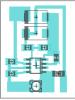
All elements will be placed on a printed circuit board measuring 115x90 mm. Why can you use foil fiberglass? The layout of all working components can be printed on a laser printer, and then everything can be transferred using an iron. The example itself is below.

Now you can move on to making transformers. And here everything is not so simple. In total you need to make two elements. For the first one you need to take:
- magnetic core with a cross-sectional area of 187 mm 2;
- three PEV-2 wires.
Moreover, one of the wires should be 0.064 mm thick, and the other - 0.185 mm. To begin with, a primary winding is created with the number of turns - 8669. Subsequent windings have fewer turns - 522.
The electrical circuit of the 220V voltage stabilizer provides for the presence of two transformers. Therefore, after assembling the first element, it is worth moving on to manufacturing the second. And for this you already need a toroidal magnetic circuit. The winding here is also made from PEV-2 wire, except that the number of turns will be equal to 455. In addition, seven taps should come from the second transformer. The first three require a wire with a diameter of 3 mm, and the remaining 4 will be made from tires with a cross-section of 18 mm². Thanks to this, the transformer will not heat up while using the stabilizer.
The task can be significantly simplified if you take two ready-made TPK-2-2 12V elements and connect them in series. All other necessary parts must be purchased in the store.
Assembly process
Assembling the stabilizer begins with installing the microcircuit on the heat sink. This can be an aluminum plate with an area of at least 15 cm2, on which triacs should also be placed. For the stabilizer to operate effectively, you cannot do without a microcontroller, for which you can use the KR1554LP5 microcircuit.
Of course, this is not a 220V circuit, but for domestic needs such a device is quite sufficient. At the next stage, you need to arrange the LEDs, and you need to take the blinking ones. However, you can use others, for example, AL307KM or L1543SRC-E, which have a bright red glow. If for some reason it is not possible to arrange them as required by the diagram, you can place them in any convenient place.
If anyone has been interested in similar assemblies before, then assembling your own stabilizer will not be difficult. This is not only an enriching experience, but also significant savings, since several thousand rubles will remain untouched.
It is necessary to correctly implement the connection diagram. And there are two ways:
- After the meter - suitable when you need to protect the entire electrical network of an apartment or house. A machine is placed directly at the output of the electric meter, and the voltage regulator is connected to its output. If necessary, you can also connect a circuit breaker to the stabilizer itself.
- Connection to a power outlet - in this case, only those devices that are connected to the regulator will be protected.
During operation, the device will heat up, and the cramped space will not provide adequate cooling. As a result, the stabilizer will quickly fail. The best option in this case is an open area.

If this is not possible for various reasons, you can build a niche specifically for the device. In this case, it is necessary to maintain at least 10 cm from the surface of the niche to the walls of the stabilizer. After assembling the device, you should check it and pay attention to the presence of any extraneous noise.
After you have successfully created 220V with your own hands, you should not think that it all ends there. It is necessary to carry out preventive maintenance every year, which involves inspecting the stabilizer and re-tensioning the contacts if necessary. This is the only way to be sure that a homemade “product” will work as effectively as its industrial counterparts.
As a conclusion
Without a doubt, making a stabilizer yourself requires certain knowledge and skills. You also need to understand exactly how such devices work and know some of the nuances. In addition, you will need to purchase all the necessary components and perform proper installation.
Perhaps all the work will seem difficult for some. Therefore, if you are not confident in your abilities, then it is better to go to the store not for parts, but for the device itself. In addition, all models have a certain warranty period.
According to the established standard GOST 29322-2014 (IEC 60038:2009), the line voltage from industrial power supplies is supplied with a frequency of 50±0.2 Hz and 230V±10%. Failure to comply with certain rules for installing electrical installations during installation work during operation causes emergency situations. In these cases, the established network parameters may deviate significantly, which negatively affects the equipment that is used as a load. Old household appliances are especially sensitive to power surges: washing machines, refrigerators, air conditioners, vacuum cleaners and hand-held power tools. To eliminate these negative phenomena, the network voltage is stabilized to 220 volts.
In cases of increased voltage, the windings of electric motors overheat, the commutators quickly wear out, breakdowns of the insulating layer and interturn short circuits in the windings are possible. When the voltage is too low, the engines start jerkily or don’t start at all, which leads to premature wear of the starting equipment elements. Contacts on magnetic starters spark and burn, lighting devices do not operate at full power and glow dimly. The best option to stabilize the voltage parameters in the network without negative consequences is the use of a booster transformer in the power supply circuit, the voltage of the secondary winding of which is added to the network voltage, bringing it closer to the established parameters.
In new types of electronic equipment, televisions, personal computers, video or audio players, switching power supplies are installed; they effectively perform the work of stabilizing elements. The switching power supply is able to maintain normal operation of the equipment at a network voltage ranging from 160 to 230V. This method reliably protects equipment from burnout of individual elements of the input circuit due to overvoltage in the network. To protect outdated types of equipment, separate voltage stabilizers are used through which the devices are connected. Such stabilizers are sold in specialized stores, but if you wish and have certain knowledge and practical skills, you can assemble the simplest circuits yourself. Many hobbyists make their own voltage stabilizer.
Types of voltage stabilizers
Depending on the load power in the network and other operating conditions, various models of stabilizers are used:
- Ferroresonance stabilizers are considered the simplest; they use the principle of magnetic resonance. The circuit includes only two chokes and a capacitor. Externally, it looks like a regular transformer with primary and secondary windings on chokes. Such stabilizers have a large weight and dimensions, so they are almost never used for household equipment. Due to their high performance, these devices are used for medical equipment;

- Servo-drive stabilizers provide voltage regulation by an autotransformer, the rheostat of which is controlled by a servo drive that receives signals from a voltage control sensor. Electromechanical models can work with heavy loads, but have a low response speed. The relay voltage stabilizer has a sectional design of the secondary winding, voltage stabilization is carried out by a group of relays, the signals for closing and opening the contacts of which come from the control board. Thus, the necessary sections of the secondary winding are connected to maintain the output voltage within the specified values. The adjustment speed is fast, but the voltage setting accuracy is low;

- Electronic stabilizers have a similar principle as relay ones, but instead of relays, thyristors, triacs or field-effect transistors are used to rectify the appropriate power, depending on the load current. This significantly increases the switching speed of the secondary winding sections. There are variants of circuits without a transformer unit, all nodes are made on semiconductor elements;

- Double conversion voltage stabilizers regulate according to the inverter principle. These models convert alternating voltage to direct voltage, then back to alternating voltage; 220V is formed at the output of the converter.

The stabilizer circuit does not convert the mains voltage. The DC-AC inverter generates 220V AC at any input voltage. Such stabilizers combine high response speed and voltage setting accuracy, but have a high price compared to previously considered options.
Electronic voltage stabilizer circuit
Let's take a closer look at how to make an electronic voltage stabilizer with your own hands for 220V, assembling the circuit and setting it up. The circuit of such a stabilizer is simple and in demand among consumers, time-tested.
Main technical characteristics:
- Network input voltage range – 160-250V;
- The output voltage after stabilization is 220V;
- The permissible power consumed by the load is 2 kW;
This power is quite enough to connect one or more valuable household appliances that are sensitive to voltage surges through the stabilizer. The weight and dimensions of the device depend on the case; the main elements, transformer and board can be placed in a ready-made box or case from other electrical equipment.
Practice shows that a homemade voltage stabilizer has some difficulties during assembly: one of the labor-intensive processes in assembling a stabilizer circuit is the manufacture of a transformer, but in our case this work can be simplified. For this circuit, transformers of the TS180-TS320 brand are ideal for a 220V voltage stabilizer; they may not be available in retail chains, but you can buy them on old TVs and in markets for 300-500 rubles.
![]()
Transformers of the TN and TPP series also showed their performance well as part of this circuit. The secondary windings of these transformers produce voltages from 24 to 36 volts and can withstand load currents of up to 8A.
Basic elements and operating principle of the circuit
A mains voltage of 160-250V is supplied to the primary winding of the transformer; after transformation, a voltage of 24-36V is supplied from the output of the secondary winding to the diode bridge VD1. The key transistor VT1 is connected to the circuit through a voltage stabilizer DA1 with a variable resistance R5, which regulates the voltage at the output of the stabilizer. Parallel stabilizer DA1 and diode bridge VD2 monitor the error voltage and amplify it.

As the network voltage increases, the voltage of the secondary winding also increases on capacitor C3, which leads to the opening of the zener diode DA1, thus shunting the voltage across resistor R7. This leads to a voltage drop at the gate of transistor VT1, it closes, and at the output contacts of the stabilized voltage XT3, XT4 its increase is limited.
When the voltage on the primary winding is reduced, a reverse reaction occurs: the voltage on the secondary winding decreases, the zener diode DA1 closes, the transistor opens, and the voltage on the secondary winding increases.
The HL1 LED shows the state of the key transistor; when it is open, additional voltage is applied to the secondary winding, and the diode lights up. Zener diode VD3 limits the voltage to the set value, protecting the transistor gate from overvoltage.
The transistor is installed on a 50x50x10 mm duralumin radiator, usually this is enough to remove heat; the power line wires must have a cross-section of at least 4 mm2, the wires in the control circuits must have a smaller cross-section.

It is advisable to install fuses FU1, FU2 at 8-10 A.
Characteristics of circuit elements
| the name of detail | Brand | Nominal value | Quantity |
|---|---|---|---|
| DA1 | Voltage reference source | TL431 | * |
| VT1 | MOSFET transistor | IRF840 | * |
| VD1 | Diode bridge | RS805 | * |
| VD2 | Rectifying diode | RL102 | **** |
| VD3 | Parallel Zener diode | KS156B | * |
| C1 | Capacitor (capacitance) | 0.1 mkf \400 V | * |
| C2 | Capacitor(electrolyte) | 10 mkf \450 V | * |
| C3 | Electrolytic capacitor | 47 mkf 25 V | * |
| C3 | Capacitor | 1000 pF | * |
| C4 | Capacitor | 0.22 mF | * |
| R1 | Resistance | 5600 Ω | * |
| R2 | Resistance | 2200 Ω | * |
| R3 | Resistance | 1500 Ω | * |
| R4 | Resistance | 8200 Ω | * |
| R5 | Variable resistor | 2200 Ω | * |
| R6 | Resistance | 1000 Ω | * |
| R7 | Resistance | 1200 Ω | * |
| T1 | Transformer | TS320 | * |
| NL1 | Light-emitting diode | AL307B | * |
| FU1, FU2 | Fuse | 10 A | ** |
| SA1 | Switch | * | |
| XT1-XT4 | Grounding Plug | ** |
To install all the elements, a printed circuit board is used, the manufacture of which requires a more detailed consideration in a separate topic. If necessary, you can order the production of a board for this circuit from specialists who do this professionally on the website http://megapcb.com/.
As you can see, the 220V voltage stabilizer circuit is easy to assemble with your own hands and works reliably.
Very important! After assembly, it is necessary to adjust the output voltage stabilization limits. To do this, connect a regular 100-200 W incandescent lamp to the output of the stabilizer, then you need to set the variable resistor R5 at the output to 225V. Then connect a larger load up to 1.5 kV and increase the voltage to 220V. Measurements can be carried out with a conventional multimeter or a pointer voltmeter can be installed in the circuit. After 10 minutes of operation at maximum load, feel how hot the transistor is and, if necessary, increase the size of the radiator.
Important! Do not forget that the transistor is attached to the radiator using heat-conducting paste through a mica gasket. For safety reasons, use a three-wire cord or a cable with a plug that has a ground terminal at the input of the stabilizer. Connect the ground wire to the neutral line on the board and case, especially when it is metal.
Video
The ideal option for the operation of electrical networks is to change the values of current and voltage both in the direction of decreasing and increasing by no more than 10% of the nominal 220 V. But since in reality surges are characterized by large changes, electrical appliances directly connected to the network are in danger of losing their design capabilities and even failure.
Using special equipment will help you avoid trouble. But since it has a very high price, many people prefer to assemble a voltage stabilizer made by themselves. How justified is such a step and what will be required to implement it?
Design and principle of operation of the stabilizer
Device design
If you decide to assemble the device yourself, you will have to look inside the body of the industrial model. It consists of several main parts:
- Transformer;
- Capacitors;
- Resistors;
- Cables for connecting elements and connecting devices.
The operating principle of the simplest stabilizer is based on the operation of a rheostat. It increases or decreases resistance depending on the current. More modern models have a wide range of functions and are able to fully protect household appliances from power surges in the network.
Types of devices and their features

Types and their applications
The classification of equipment depends on the methods used to regulate the current. Since this quantity represents the directional movement of particles, it can be influenced in one of the following ways:
- Mechanical;
- Impulse.
The first is based on Ohm's law. Devices whose operation is based on it are called linear. They include two elbows that are connected using a rheostat. The voltage applied to one element passes through the rheostat and thus appears on the other, from which it is supplied to consumers.
Devices of this type allow you to very simply set the output current parameters and can be upgraded with additional components. But it is impossible to use such stabilizers in networks where the difference between the input and output current is large, since they will not be able to protect household appliances from short circuits under heavy loads.
Let's watch the video, the operating principle of the pulse device:
Pulse models operate on the principle of amplitude modulation of current. The stabilizer circuit uses a switch that breaks it at certain intervals. This approach allows current to be evenly accumulated in the capacitor, and after it is fully charged, further to devices.
Unlike linear stabilizers, pulse ones do not have the ability to set a specific value. There are step-up and step-down models on sale - this is an ideal choice for the home.
Voltage stabilizers are also divided into:
- Single-phase;
- Three-phase.
But since most household appliances operate from a single-phase network, in residential premises they usually use equipment belonging to the first type.
Let's start assembling: components, tools
Since a triac device is considered the most effective, in our article we will look at how to independently assemble just such a model. It should be immediately noted that this DIY voltage stabilizer will equalize the current provided that the input voltage is in the range from 130 to 270V.
The permissible power of devices connected to such equipment cannot exceed 6 kW. In this case, the load will be switched in 10 milliseconds.
As for components, to assemble such a stabilizer you will need the following elements:
- Power unit;
- Rectifier for measuring voltage amplitude;
- Comparator;
- Controller;
- Amplifiers;
- LEDs;
- Load turn-on delay unit;
- Autotransformer;
- Optocoupler switches;
- Switch-fuse.
The tools I will need are a soldering iron and tweezers.
Manufacturing stages
To assemble a 220V voltage stabilizer for your home with your own hands, you first need to prepare a printed circuit board measuring 115x90 mm. It is made of foil fiberglass. The layout of the parts can be printed on a laser printer and transferred to the board using an iron.
Let's watch the video, a homemade simple device:

electrical circuit diagram
- magnetic core with a cross-sectional area of 1.87 cm²;
- three PEV-2 cables.
The first wire is used to create one winding, and its diameter is 0.064 mm. The number of turns should be 8669.
The two remaining wires will be needed to make other windings. They differ from the first one in diameter being 0.185 mm. The number of turns for these windings will be 522.
If you want to simplify your task, you can use two ready-made TPK-2-2 12V transformers. They are connected in series.
In the case of making these parts yourself, after one of them is ready, they move on to creating the second. It will require a toroidal magnetic circuit. For the winding, choose the same PEV-2 as in the first case, only the number of turns will be 455.
Also in the second transformer you will have to make 7 taps. Moreover, for the first three, a wire with a diameter of 3 mm is used, and for the rest, buses with a cross-section of 18 mm² are used. This will help prevent the transformer from heating up during operation.

connection of two transformers
It is better to purchase all other components for a device you create yourself in a store. Once everything you need has been purchased, you can begin assembly. It is best to start by installing a microcircuit that acts as a controller on a heat sink, which is made of aluminum platinum with an area of more than 15 cm². Triacs are also mounted on it. Moreover, the heat sink on which they are supposed to be installed must have a cooling surface.
If assembling a 220V triac voltage stabilizer with your own hands seems complicated to you, then you can opt for a simpler linear model. It will have similar properties.
The effectiveness of a handmade product
What pushes a person to make this or that device? Most often - its high cost. And in this sense, a voltage stabilizer assembled with your own hands is, of course, superior to a factory model.
The advantages of homemade devices include the possibility of self-repair. The person who assembled the stabilizer understood both its operating principle and structure and therefore will be able to eliminate the malfunction without outside help.
In addition, all the parts for such a device were previously purchased in the store, so if they fail, you can always find a similar one.
If we compare the reliability of a stabilizer assembled with our own hands and manufactured at an enterprise, then the advantage is on the side of factory models. At home, it is almost impossible to develop a model with high performance, since there is no special measuring equipment.
Conclusion
There are different types of voltage stabilizers, and some of them are quite possible to make with your own hands. But to do this, you will have to understand the nuances of the operation of the equipment, purchase the necessary components and carry out their proper installation. If you are not confident in your abilities, then the best option is to purchase a factory-made device. Such a stabilizer costs more, but the quality is significantly superior to models assembled independently.
The optimal way to operate electrical networks is considered to be changing the current functions, as well as the required voltage, by 10% from 220V. However, since the surges change quite often, electrical devices that are directly connected to the network are at risk of breakdown.
To eliminate such troubles, it is necessary to install certain equipment. And since the magazine device has a fairly high cost, naturally many people assemble the stabilizer with their own hands.

Is such a decision justified and what is required to make it a reality?

The principle of operation of the stabilizer
Having decided to create a homemade stabilizer, as in the photo, you need to look at the inside of the case, which consists of certain parts. The operating principle of a conventional device is based directly on the functioning of a rheostat, which increases or decreases resistance.


In addition, the proposed models have a variety of functions, and can also fully protect equipment from unwanted surge voltage surges in the network.

Equipment is classified depending on the methods used to regulate the current. Since the value is the directional movement of particles, it can be influenced accordingly by a mechanical or pulse method.

The first one works according to Ohm's law. Devices whose operation is based on it are called linear. They include several bends, combined by means of a rheostat.

The voltage that is supplied to one part passes through a rheostat, ending up in a similar way to another, from which it is transmitted to the consumer.

This type of device makes it possible to set the required current parameters as accurately as possible and can easily be upgraded with special units.

However, it is unacceptable to use such stabilizers in networks where there is a large difference between the currents, since they will not fully protect equipment from short circuits during overloads.

Pulse options operate using the amplitude current modulation method. The circuit uses a switch that breaks it after the required period of time. This approach makes it possible to accumulate the required current in the capacitor as evenly as possible, and after charging is completed, and then to the devices.


Let's start assembly
Since the most effective device is a triac device, let’s talk about how to make a similar stabilizer with your own hands.

It is important to emphasize that this type of model will be able to equalize the supplied current under the condition that the voltage is in the range of 130-270 V. Components will also be required. Tools you need are tweezers and a soldering iron.

Stages of production
According to the detailed instructions on how to mount the stabilizer, first of all, you should prepare a printed circuit board of the required size. It is created from special foil-coated fiberglass. The microcircuit for the arrangement of elements can be in a printed format, or transferred to the board using an iron.

Then, the scheme for creating a simple stabilizer provides for the direct assembly of the device. For this element you will need a magnetic circuit and several cables. One wire with a diameter of 0.064 mm is used to make the winding. The number of required turns reaches 8669.

The remaining two wires are used to create the remaining windings, which, in comparison with the first option, have a diameter of 0.185 mm. The number of turns arranged for these windings is at least 522.

If it is necessary to simplify the task, it is preferable to use series-connected transformers of the TPK-2-2 12V brand.

When producing these parts independently, after completing the creation of one of them, they proceed to the production of another. For these purposes, a troidal magnetic circuit will be required. PEV-2 with a number of turns of 455 is also suitable as a winding.


In addition, by step-by-step manual production of the stabilizer in the second device, 7 bends should be made. In this case, for several three, a wire of 3 mm in diameter is used, for others, buses with a cross-section of 18 mm2 are used. This will make it possible to eliminate unwanted heating of the device during the working process.

The remaining items should be purchased at a specialized retail outlet. Once everything you need has been purchased, you should assemble the device.

Work should begin with the installation of the necessary microcircuit, which acts as a controller on the heat sink being installed, made of platinum. In addition, triacs are installed on it. Then flashing LEDs are mounted on the board.

If creating triac devices is a difficult task for you, then it is recommended to choose a linear version, characterized by similar properties.

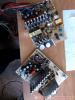
Photos of do-it-yourself stabilizers