How to increase DC and AC voltage. How to obtain a non-standard voltage Final assembly of a pulse voltage converter
After my articles on low-power inverters for charging mobile devices, I received personal messages on the forum asking for a 3.7-5 Volt inverter circuit. After a short search on the Internet, I realized that there were no normal circuits; everything that was available was assembled using specialized drivers - they are inaccessible to many users (especially beginners). Therefore, I decided to create perhaps the simplest inverter circuit that is capable of charging all portable electronic devices with a built-in 3.7-volt lithium-ion battery.
The universal output voltage rating of 5 Volts makes it possible to charge all known mobile phones, players and tablet computers, in other words, the output voltage was chosen to be 5 Volts.
The main parameters are as follows
Input voltage 3.5-6 Volts
Current consumption when the phone is connected is no more than 500mA
Output voltage 5 Volts
Output current no more than 80 mA
Later I carried out some experiments, as a result I managed to obtain an output current of up to 120 mA with a consumption of 650 mA, although the circuit can deliver much more, for this it is necessary to increase the cross-section of the wires in both windings, but at the same time the consumption increases sharply and the efficiency of the converter decreases.
As a rectifier, it is advisable to use a Schottky diode or any pulse diodes with an operating voltage of more than 20 Volts and a current above 500 mA; the most common ones are FR107/207 and any others with the specified parameters.
Although the power of such an inverter is not great, the phone charges quite quickly, almost like using a standard charger.
At the output of the charging inverter there is also an electrolytic capacitor to smooth out noise after the rectifier, after which the voltage is supplied to a linear voltage stabilizer made on the 7805 microcircuit, at the output of which we obtain a stable voltage of 5 Volts; a zener diode in front of the microcircuit is not needed in this case, since the output voltage is after the diode does not exceed 15 Volts.
The battery in my case is used from a tablet computer with a capacity of 2000 mAh, the capacity is enough for 4-5 hours of continuous operation of the inverter.
Then I decided to supplement the charger with a silicon photocell. Such a module delivers voltage up to 9 Volts at a maximum current of 50 mA, even in cloudy weather the voltage at the module output is at least 7 Volts at a current of 30-35 mA. The module is not the most powerful, but as an option it is quite suitable for recharging the battery.
The inverter was designed specifically for beginner radio amateurs who have become interested in radio equipment not long ago. I’m sure anyone can assemble such a charger; it’s a simple, cheap and useful thing, it works flawlessly and does not require any adjustment.
Boost converter 3.6 - 5 volts on MC34063
There are plenty of articles written about converters based on MC34063 and similar microcircuits. Why write another one? Let's be honest, we wrote it to lay out a printed circuit board. Perhaps someone will consider it successful or are simply too lazy to draw their own.

Such a converter may be needed, for example, to power some homemade product or measuring instrument from a lithium battery. In our case, this is the power supply of the dosimeter from the Chinese 1.5A/h. The circuit is a standard one, from the datasheet, a boost converter.

The printed circuit board turned out to be small, only 2*2.5 cm. You can do less. All parts, as planned, are SMD. However, finding a ceramic SMD capacitor with a capacity of less than 1 nF turned out to be not so easy; I had to install a lead capacitor. It also turned out to be difficult to find a relatively small inductor of the required inductance that does not saturate at the required current. As a result, it was decided to use a higher frequency - about 100 kHz and a 47 µH inductor. As a result, it is only one third larger than the dimensions of the board.

The voltage divider for stabilizing 5 volts was successfully made from 3 and 1 kOhm resistors. If you try, you can carefully solder a multi-turn potentiometer in their place, as we did in the NCP3063 converter, in order to be able to adjust the voltage.
The scope of application of this circuit is not limited to powering devices. It can be successfully used in homemade flashlights, chargers, power banks, in a word - anywhere where you need to convert one voltage value to another. This chip is not very powerful, but it can handle most applications.
However, when using pulse converters to power measuring instruments and sensitive equipment, you should remember the noise level that they create along the power circuits. There is an opinion that for circuits that are very sensitive to such things, the only solution is to use a linear stabilizer between the converter and the circuit directly fed by it. In our case, we obtained the minimum ripple level using the maximum capacitance of the capacitor at the output of the converter that we could find. It turned out to be tantalum at 220 µF. There is space on the board to install several ceramic capacitors at the output if necessary.
The 3.6 - 5 volt boost converter on the MC34063 showed good stable operation and can be recommended for use.
Not everyone has heard that lithium-ion AA batteries have not only the standard 3.7 volts, but there are models that give the usual one and a half, like nickel-cadmium ones. Yes, the chemistry of the cans itself does not allow the creation of 1.5-volt cells, so there is a step-down stabilizer inside. This way you get a classic rechargeable battery, with a standard voltage for most devices and, most importantly, toys. These batteries have the advantage that they charge very quickly and are more powerful in capacity. Therefore, we can safely assume an increase in the popularity of such batteries. Let's examine the test sample and analyze its filling.
The battery itself looks like regular AA cells, except for the top positive terminal. There is a recessed ring around it on top, which provides a direct connection to the Li-ion cell for.

After tearing off the label, we were greeted with a simple steel casing. Wanting to disassemble the cell with minimal risk of an internal short circuit, a small pipe cutter was used to carefully disassemble the weld.

The printed circuit board, which produces 3.7 - 1.5 volts, is located inside the cover.


This converter uses a 1.5 MHz DC-DC inverter to provide 1.5 V output. Judging by the datasheet, this is a fully integrated converter with all power semiconductor components. The converter is designed for 2.5-5.5 volt input, that is, within the operating range of the Li-ion cell. In addition, it has a self-current consumption of only 20 microamps.


The battery has a protection circuit located on a flexible circuit board that surrounds the Li-ion cell. It uses the XB3633A chip, which, like the inverter, is a fully integrated device; there are no external MOSFETs to disconnect the cell from the rest of the circuit. In general, with all this accompanying electronics, the lithium cell turned into an ordinary full-fledged 1.5 V battery.
To power electrical appliances, it is necessary to ensure the nominal values of the power supply parameters stated in their documentation. Of course, most modern electrical appliances operate on 220 Volt AC power, but it happens that you need to provide power to devices for other countries where the voltage is different or to power something from the car’s on-board network. In this article we will look at how to increase DC and AC voltage and what is needed for this.
AC Voltage Boost
There are two ways to increase the alternating voltage - use a transformer or an autotransformer. The main difference between them is that when using a transformer there is galvanic isolation between the primary and secondary circuits, while when using an autotransformer there is no galvanic isolation.
Interesting! Galvanic isolation is the absence of electrical contact between the primary (input) circuit and the secondary (output) circuit.
Let's look at frequently asked questions. If you find yourself outside the borders of our vast homeland and the electrical networks there differ from our 220 V, for example, 110 V, then to raise the voltage from 110 to 220 Volts you need to use a transformer, for example, such as is shown in the figure below:
It should be said that such transformers can be used “in any direction.” That is, if the technical documentation of your transformer says “the voltage of the primary winding is 220V, the secondary is 110V,” this does not mean that it cannot be connected to 110V. Transformers are reversible, and if the same 110V is applied to the secondary winding, 220V or another increased value will appear on the primary winding, proportional to the transformation ratio.
The next problem that many people face is that this is especially common in private homes and garages. The problem is related to the poor condition and overload of power lines. To solve this problem, you can use LATR (laboratory autotransformer). Most modern models can both lower and smoothly increase network parameters.

Its diagram is shown on the front panel, and we will not dwell on explanations of the principle of operation. LATRs are sold in different capacities, the one in the figure is approximately 250-500 VA (volt-amperes). In practice, there are models up to several kilowatts. This method is suitable for supplying nominal 220 Volts to a specific electrical appliance.
If you need to cheaply increase the voltage throughout the house, your choice is a relay stabilizer. They are also sold in different capacities and the range is suitable for most typical applications (3-15 kW). The device is also based on an autotransformer. We talked about this in the article to which we referred.

DC circuits
Everyone knows that transformers do not work on direct current, then how can the voltage be increased in such cases? In most cases, the constant is increased using a field-effect or bipolar transistor and a PWM controller. In other words, it is called a transformerless voltage converter. If these three main elements are connected as shown in the figure below and a PWM signal is applied to the base of the transistor, then its output voltage will increase Ku times.
Ku=1/(1-D)

We will also consider typical situations.
Let's say you want to backlight your keyboard using a small piece of LED strip. The power of a smartphone charger (5-15 W) is quite enough for this, but the problem is that its output voltage is 5 Volts, and common types of LED strips operate on 12 V.
Then how to increase the voltage on the charger? The easiest way to boost is with a device such as a “dc-dc boost converter” or “pulse boost DC-DC converter.”

Such devices allow you to increase the voltage from 5 to 12 Volts, and are sold both with a fixed value and adjustable, which in most cases will allow you to increase from 12 to 24 and even up to 36 Volts. But keep in mind that the output current is limited by the weakest element of the circuit, in the situation under discussion - the current on the charger.
When using the specified board, the output current will be less than the input current by as many times as the output voltage has increased, without taking into account the efficiency of the converter (it is around 80-95%).
Such devices are built on the basis of MT3608, LM2577, XL6009 microcircuits. With their help, you can make a device for checking the regulator relay not on the car’s generator, but on the desktop, adjusting the values from 12 to 14 Volts. Below you see a video test of such a device.
Interesting! DIY enthusiasts often ask the question “how to increase the voltage from 3.7 V to 5 V in order to make a Power bank on lithium batteries with your own hands?” The answer is simple - use the FP6291 converter board.

On such boards, the purpose of the contact pads for connection is indicated using silk-screen printing, so you do not need a diagram.

Another situation that often arises is the need to connect a 220V device to a car battery, and it happens that outside the city you really need to get 220V. If you don’t have a gasoline generator, use a car battery and an inverter to increase the voltage from 12 to 220 Volts. A 1 kW model can be purchased for $35 - this is an inexpensive and proven way to connect a 220V drill, grinder, boiler or refrigerator to a 12V battery.

If you are a truck driver, the above inverter will not be suitable for you, due to the fact that your on-board network is most likely 24 Volts. If you need to increase the voltage from 24V to 220V, then pay attention to this when purchasing an inverter.

Although it is worth noting that there are universal converters that can operate on both 12 and 24 volts.
In cases where you need to obtain a high voltage, for example, increase it from 220 to 1000V, you can use a special multiplier. Its typical diagram is shown below. It consists of diodes and capacitors. You will get a direct current output, keep this in mind. This is the Latour-Delon-Grenacher doubler:

And this is what the circuit of an asymmetrical multiplier (Cockroft-Walton) looks like.

With its help, you can increase the voltage by the required number of times. This device is built in cascades, the number of which determines how many volts you get at the output. The following video describes how the multiplier works.
In addition to these circuits, there are many others; below are quadrupler circuits, 6- and 8-fold multipliers, which are used to increase the voltage:


In conclusion, I would like to remind you about safety precautions. When connecting transformers, autotransformers, as well as working with inverters and multipliers, be careful. Do not touch live parts with bare hands. Connections should be made with no power supplied to the device, and should not be used in damp areas where water or splashes may occur. Also, do not exceed the current of the transformer, converter or power supply declared by the manufacturer if you do not want it to burn out. We hope the tips provided will help you increase the voltage to the desired value! If you have any questions, ask them in the comments below the article!
You probably don't know:
Like( 0 ) I do not like( 0 )
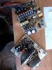
I present a review of a micro-power voltage converter, which is of little use.
Built quite well, compact size 34x15x10mm 

Stated:
Input voltage: 0.9-5V
With one AA battery, output current up to 200mA
With two AA batteries, output current 500~600mA
Efficiency up to 96%
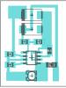
Real converter circuit 
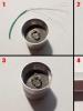
What immediately catches your eye is the very small capacitance of the input capacitor - only 0.15 µF. Usually they set it more than once in 100, apparently they naively count on the low internal resistance of the batteries :) Well, they installed this one and God bless it, if necessary, you can change it - I immediately set it to 10 μF. Below in the photo is the original capacitor. 
The dimensions of the throttle are also very small, which makes you think about the veracity of the declared characteristics
A red LED is connected to the converter input, which begins to glow when the input voltage is more than 1.8V
The test was carried out for the following stabilized input voltages:
1.25V - voltage of Ni-Cd and Ni-MH batteries
1.5V - voltage of one galvanic cell
3.0V - voltage of two galvanic cells
3.7V - Li-Ion battery voltage
At the same time, I loaded the converter until the voltage dropped to a reasonable 4.66V
Open circuit voltage 5.02V
- 0.70V - the minimum voltage at which the converter starts idling. The LED naturally does not light up - there is not enough voltage.
- 1.25V no-load current 0.025mA, maximum output current only 60mA at a voltage of 4.66V. The input current is 330mA, the efficiency is about 68%. The LED naturally does not light up at this voltage. 
- 1.5V no-load current 0.018mA, maximum output current 90mA at a voltage of 4.66V. The input current is 360mA, the efficiency is about 77%. The LED naturally does not light up at this voltage. 
- 3.0V no-load current 1.2mA (consumes mainly the LED), maximum output current 220mA at a voltage of 4.66V. The input current is 465mA, the efficiency is about 74%. The LED glows normally at this voltage. 
- 3.7V idle current 1.9mA (consumes mainly the LED), maximum output current 480mA at a voltage of 4.66V. The input current is 840mA, the efficiency is about 72%. The LED glows normally at this voltage. The converter begins to warm up slightly. 
For clarity, I summarized the results in a table. 
Additionally, at an input voltage of 3.7V, I checked the dependence of the conversion efficiency on the load current
50mA - efficiency 85%
100mA - efficiency 83%
150mA - efficiency 82%
200mA - efficiency 80%
300mA - efficiency 75%
480mA - efficiency 72%
As is easy to see, the lower the load, the higher the efficiency
Falls far short of the stated 96%
Output voltage ripple at 0.2A load 
Output voltage ripple at 0.48A load 
As is easy to see, at maximum current the ripple amplitude is very large and exceeds 0.4V.
Most likely this is due to a small output capacitor with a high ESR (measured 1.74 Ohm)
Operating conversion frequency about 80 kHz
I additionally soldered 20 µF ceramics to the output of the converter and received a 5-fold reduction in ripple at maximum current! 

Conclusion: the converter is very low-power - this should definitely be taken into account when choosing it to power your devices