Electric motor three-phase star-delta. The choice of the connection scheme of the phases of the electric motor. Triangle connection and its advantages
Turbine compressor rotor
As you know, three-phase asynchronous electric (el.) Motors with a squirrel-cage rotor are connected according to the star or delta circuit, depending on the line voltage for which each winding is designed.
When starting especially powerful email. delta-connected motors, increased starting currents are observed, which in overloaded networks create a temporary voltage drop below the permissible limit.
This phenomenon is due to the design features of asynchronous email. engines in which a massive rotor has a sufficiently large inertia, and when it is spinning up, the motor operates in overload mode. The start of the electric motor becomes more difficult if there is a load with a large mass on the shaft - the rotors of turbine compressors, centrifugal pumps or the mechanisms of various machine tools.
Way to reduce the starting currents of the electric motor
To reduce current overloads and voltage drops in the network, a special method of connecting a three-phase electric is used. an engine that switches from a star to a delta as it speeds up.
 Connection of motor windings: star (left) and delta (right)
 When connecting star-connected windings of a motor designed for delta connection to a three-phase network, the voltage given to each winding is 70% less than the nominal value. Accordingly, the current at the start of el. motor will be smaller, but it should be remembered that the starting torque will also be smaller.
Therefore, star-delta switching cannot be applied to electric motors that initially have a non-inertial load on the shaft, such as the weight of a winch load or the resistance of a reciprocating compressor.
 It is unacceptable to switch modes with an electric motor standing on a reciprocating compressor
 To work as part of such units, which have a large load at the time of start-up, special three-phase el are used. motors with a phase rotor, in which starting currents are regulated using rheostats.
Star-delta switching can only be used for electric motors with a freely rotating load on the shaft - fans, centrifugal pumps, shafts of machine tools, centrifuges and other similar equipment.
 Centrifugal pump with asynchronous electric motor
 Implementation of changing the modes of connecting the motor windings
Obviously, in order to start a three-phase electric motor in a star mode, followed by switching to a delta winding connection, it is necessary to use several three-phase contactors in the starter.
 A set of contactors in a star-delta starter
 In this case, it is necessary to block the instantaneous operation of these contactors, and a short-term switching delay must also be provided so that the star connection is guaranteed to turn off before the delta turns on, otherwise a three-phase short circuit will occur.
Therefore, the time relay (RT), which is used in the circuit to set the switching interval, must also provide a delay of 50-100 ms so that a short circuit does not occur.
Ways to Implement Switch Delay
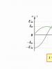
 Switching time diagram
 There are several principles for implementing a delay using:

 Manual mode switch
 Classic scheme
This system is quite simple, unpretentious and reliable, but has a significant drawback, which will be described below and requires the use of a bulky and obsolete time relay.
This RT provides tripping delay due to the magnetized core, which takes some time to demagnetize.
 Electromagnetic delay time relay
 It is necessary to mentally walk through the current flow circuits in order to understand the operation of this circuit.
 Classic switching circuit with current and time relays
 After turning on the three-phase circuit breaker AB, the starter is ready for operation. Through the normally closed contacts of the "Stop" button, and the contact of the "Start" button closed by the operator, the current flows through the coil of the KM contactor. The power contacts of the KM are kept in the on state by "self-pickup", thanks to the BKM contact.
 On the fragment of the above diagram, the red arrow indicates the shunt contact
 The KM relay is necessary to enable the engine to be turned off with the Stop button. The impulse from the "Start" button also passes through the normally closed BKM1 and RV, starting the KM2 contactor, the main contacts of which provide voltage to the star-type winding connection - the rotor is spinning up.
Since at the moment of starting KM2 the BKM2 contact opens, KM1, which ensures that the triangle connection of the windings is switched on, cannot work in any way.
 Contactors providing star (KM2) and delta (KM1) connection
 Starting current overloads el. the motor is forced to operate almost instantly RT, included in the circuits of current transformers TT1, TT2. In this case, the control circuit of the KM2 coil is shunted by the RT contact, blocking the operation of the RV.
Simultaneously with the start of KM2, with the help of its additional normally open contact BKM2, a time relay is started, the contacts of which are switched, but KM1 does not operate, since BKM2 is open in the circuit of the KM1 coil.
 Turning on the time relay - green arrow, switching contacts - red arrows
 As the speed increases, the starting currents decrease and the contact RT in the KM2 control circuit opens. Simultaneously with the disconnection of the power contacts that provide power to the star connection of the windings, the BKM2 closes in the KM1 control circuit and the BKM2 opens in the RV power circuit.
But, since the RV turns off with a delay, this time is enough for its normally open contact in the KM1 circuit to remain closed, due to which KM1 self-picks up, connecting the windings with a triangle.
 Normally open self-pickup contact KM1
 The disadvantage of the classical scheme
If, due to incorrect calculation of the load on the shaft, it cannot gain momentum, then the current relay in this case will not allow the circuit to switch to delta mode. Long-term operation an asynchronous motor in this mode of starting overload is highly undesirable, the windings will overheat.
 Overheated motor windings
 Therefore, in order to prevent the consequences of an unforeseen increase in load when starting a three-phase el. motor (worn bearing or foreign objects entering the fan, contamination of the pump impeller), you should also connect a thermal relay to the power supply circuit of the electric motor. engine after the KM contactor (not indicated in the diagram) and install the temperature sensor on the casing.
 Appearance and main components of the thermal relay
 If a timer (modern RV) is used to switch modes, which occurs within a set time interval, then when the motor windings are turned on in a triangle, a set of nominal revolutions occurs, provided that the load on the shaft corresponds to the technical conditions for the operation of the electric motor.
 Switching modes using a modern time relay CRM-2T
 The operation of the timer itself is quite simple - first, the star contactor is turned on, and after an adjustable time, this contactor is turned off, and with some also adjustable delay, the triangle contactor is turned on.
The correct specifications for the use of switching winding connections.
When starting any three-phase el. of the motor, the most important condition must be observed - the moment of load resistance must always be less than the starting torque, otherwise the electric motor simply will not start, and its windings will overheat and burn out, even if the star start mode is used, in which the voltage is lower than the nominal.
Even if there is a freely rotating load on the shaft, the starting torque when connected by a star may not be enough and el. the engine will not pick up the speed at which the switch to the triangle mode should be carried out, since the resistance of the medium in which the mechanisms of the units rotate (fan blades or sediment impeller) will increase as the rotation speed increases.
In this case, if the current relay is excluded from the circuit, and the switching of modes is carried out according to the timer setting, then at the moment of transition to the triangle, all the same current surges of almost the same duration will be observed as during starting from a stationary state of the rotor.
 Comparative characteristics of direct and transient engine starts with a load on the shaft
 Obviously, such a star-delta connection will not give any positive results with an incorrectly calculated starting torque. But at the moment the contactor is turned off, which provides a star connection, with insufficient engine speed, due to self-induction, an overvoltage surge will be observed in the network, which can damage other equipment.
Therefore, using star-delta switching, it is necessary to make sure that such a connection of a three-phase asynchronous el is expedient. engine and recheck load calculations.
Today, asynchronous electric motors are popular due to their reliability, excellent performance and relatively low cost. Motors of this type are designed to withstand heavy mechanical loads. In order for the unit to start up successfully, it must be connected correctly. For this, star and delta connections are used, as well as their combination.
Connection types
The design of the electric motor is quite simple and consists of two main elements - fixed stator and located inside, rotating rotor. Each of these parts has its own windings that conduct current. The stator is laid in special grooves with the obligatory observance of a distance of 120 degrees.
The principle of operation of the motor is simple - after turning on the starter and applying voltage to the stator, a magnetic field arises that causes the rotor to rotate. Both ends of the windings are brought out to the junction box and arranged in two rows. Their conclusions are marked with the letter "C" and receive a digital designation ranging from 1 to 6.
To connect them, you can use one of three methods:
- "Star";
- "Triangle";
- "Star-triangle".
However, the combined circuit cannot be used if it is necessary to reduce the starting current, but at the same time a large torque is required. In this case, an electric motor with a phase rotor equipped with a rheostat should be used.
If we talk about the advantages of combining two connection methods, then two can be noted:
- Soft start increases service life.
- You can create two power levels of the unit.
Today, the most widely used electric motors are designed to work in networks of 220 and 380 volts. It is on this that the choice of the connection scheme depends. Thus, the "triangle" is recommended to be used at a voltage of 220 V, and the "star" - at 380 V.
A three-phase electric motor is an electrical machine designed to operate on alternating current. Such an engine consists of a stator and a rotor. The stator has three windings shifted one hundred and twenty degrees. When a three-phase voltage appears in the winding circuit, magnetic fluxes are formed at the poles, and the rotor rotates. Electric motors are either synchronous or asynchronous. Three-phase have been widely used in industry and in everyday life. Such motors are single-speed, in which case the motor windings are connected according to the "star" or "delta" scheme, and multi-speed. The last units are switchable, in this case there is a transition from one connection scheme to another.
Three-phase electric motors are divided according to the winding connection schemes. There are two connection schemes - a star connection and a delta connection. The connection of the motor windings according to the "star" type is a connection of the ends of the motor windings to one point (zero node): an additional output is obtained - zero. The free ends are connected to the phases of the 380 V electric network. Outwardly, such a connection resembles a three-pointed star. The photo shows the following diagram: a “star” and “triangle” connection. The connection of the electric motor windings according to the “triangle” type is a winding: the end of the first is connected to the beginning of the second winding, the end of the second to the beginning of the third, and the end of the third to the beginning of the first. A three-phase voltage is applied to the winding connection nodes. With this connection of the windings, there is no zero output. Outwardly, it resembles a triangle.

The connection "star" and "delta" are equally common, they do not have significant differences. To connect the windings according to the "star" type (when the engine is running in rated mode), the line voltage must be greater than when connected according to the "delta" type. Therefore, in the characteristics of a three-phase motor, they indicate as follows: 220/380 V or 127/220 V. If necessary, it is required to connect to the rated winding in a “star” type, and the rated voltage of the motor will be 380/660 V (by the “triangle” type).
It should be noted that a combined star and delta connection is often used. This is done to make the motor start more smoothly. When starting, a star connection is used, and then a special relay switches to a delta connection, thus reducing the starting current. Such schemes are recommended for starting high-power electric motors that require a large starting current. It is important to remember that in this case the starting current exceeds the rated current by seven times.

There are other combinations when connecting electric motors, for example, a star and delta connection can be replaced by a double, triple star, as well as other connection options. Such methods are used for multi-speed (two-, four-, etc.) electric motors.
Asynchronous electric motor - electromechanical equipment, widespread in various fields of activity, and therefore familiar to many. Meanwhile, even taking into account the close relationship with the people, a rare "electrician himself" is able to reveal the whole ins and outs of these devices. For example, not every "pliers holder" can give accurate advice: how to connect the motor windings with a "triangle"? Or how to set the jumpers of the motor winding connection scheme with a “star”? Let's try to uncover these two simple and at the same time complex questions.
As Anton Pavlovich Chekhov used to say:
Repetition is the mother of learning!
It is logical to start repeating the topic of electric induction motors with a detailed review of the design. built on the basis of the following structural elements:
- aluminum case with cooling elements and mounting chassis;
- stator - three coils wound with copper wire on an annular basis inside the body and placed opposite one another under an angular radius of 120º;
- rotor - a metal blank, rigidly fixed on the shaft, inserted into the annular base of the stator;
- thrust bearings for the rotor shaft - front and rear;
- housing covers - front and rear, plus an impeller for cooling;
- BRNO - the upper part of the housing in the form of a small rectangular niche with a lid, where the terminal block for fastening the stator winding leads is located.
Here is the whole structure. Most of the asynchronous electric motors are the prototype of just such a design. True, sometimes there are instances of a slightly different configuration. But this is already an exception to the rule.
Designation and wiring of stator windings
There is still a fairly large number of asynchronous electric motors, where the designation of the stator windings is made according to an outdated standard.
This standard provided for marking with the symbol “C” and adding a number to it - the number of the output of the winding, indicating its beginning or end.
In this case, the numbers 1, 2, 3 always refer to the beginning, and the numbers 4, 5, 6, respectively, indicate the ends. For example, markers "C1" and "C4" indicate the beginning and end of the first stator winding.
 Marking of the end parts of the conductors output to the BRNO terminal block: A - an outdated designation, but still found in practice; B - a modern designation, traditionally present on the markers of the conductors of new motors
 Modern standards have changed this marking. Now the symbols noted above have been replaced by others corresponding to the international standard (U1, V1, W1 - starting points, U2, V2, W2 - end points) and are traditionally found when working with new generation asynchronous engines.
The conductors emanating from each of the stator windings are brought out to the terminal box area, which is located on the motor housing and connected to an individual terminal.
In total, the number of individual terminals is equal to the number of lead out initial and final wires of the common winding. Usually it is 6 conductors and the same number of terminals.
 This is how the terminal block of the standard configuration engine looks like. Six terminals are connected with brass (copper) jumpers before connecting the motor to the appropriate voltage
 Meanwhile, there are also variations in the wiring of conductors (rarely and usually on old motors), when 3 wires are brought out to the BRNO area and only 3 terminals are present.
How to connect "star" and "triangle"?
Connection of an asynchronous electric motor with six conductors brought to the terminal box is carried out using a standard technique using jumpers.
By properly placing jumpers between individual terminals, it is easy and simple to establish the desired circuit configuration.
So, in order to create an interface for connecting with a “star”, the initial conductors of the windings (U1, V1, W1) should be left single on individual terminals, and the terminals of the end conductors (U2, V2, W3) should be connected to each other with jumpers.
 Connection scheme "star". It has a high line voltage requirement. Gives a smooth running of the rotor in start mode
 If you need to create a “triangle” connection scheme, the jumper placement option changes. To connect the stator windings with a triangle, you need to connect the initial and end conductors of the windings according to the following scheme:
- initial U1 - terminal W2
- initial V1 - terminal U2
- initial W1 - terminal V2
 Connection scheme "triangle". A distinctive feature is high starting currents. Therefore, often the motors according to this scheme are pre-started on the "star" with the subsequent transfer to the operating mode
 Connection for both circuits, of course, is assumed to be a three-phase network with a voltage of 380 volts. There is no particular difference when choosing one or another circuit option.
However, the large line voltage requirement for the star circuit must be taken into account. This difference, in fact, shows the marking "220/380" on the technical plate of the motors.
The star-delta series connection option seems to be the optimal starting method for a 3-phase AC induction motor. This option is often used to soft start the motor at low initial currents.
Initially, the connection is organized according to the "star" scheme. Then, after a certain period of time, a connection to the "triangle" is performed by instantaneous switching.
Connection with technical information
Each asynchronous electric motor is necessarily equipped with a metal plate, which is fixed on the side of the housing.
Such a plate is a kind of equipment identification panel. It contains all the necessary information required for the correct installation of the product in the AC mains.
 Technical plate on the side of the engine housing. All important parameters required to ensure the normal operation of the electric motor are noted here.
 This information should not be neglected, including the motor in the electric circuit. Violations of the conditions marked on the information plate are always the first causes of motor failure.
What is indicated on the technical plate of an asynchronous electric motor?
- Type of motor (in this case, asynchronous).
- Number of phases and operating frequency (3ph / 50Hz).
- Winding switching circuit and voltage (triangle / star, 220/380).
- Operating current (delta / star)
- Power and number of revolutions (kW / rpm).
- Efficiency and COS φ (% / coefficient).
- Mode and class of insulation (S1 - S10 / A, B, F, H).
- Manufacturer and year of manufacture.
Turning to the technical plate, the electrician already knows in advance under what conditions it is permissible to turn on the motor in the network.
From the point of view of connecting with a “star” or “triangle”, as a rule, the existing information lets the electrician know that the “triangle” connection is correct in the 220V network, and the asynchronous electric motor should be connected to the 380V line with a “star”.
The motor should be tested or operated only if it is wired through a protective one. At the same time, the automaton introduced into the circuit of the asynchronous electric motor should be correctly selected according to the cut-off current.
Three-phase asynchronous electric motor in a 220V network
Theoretically and practically the same, an asynchronous electric motor, designed to be connected to the network through three phases, can operate in a single-phase 220V network.
As a rule, this option is relevant only for motors with a power not exceeding 1.5 kW. This limitation is explained by a banal shortage of the capacity of an additional capacitor. High power requires a capacitance for high voltages, measured in hundreds of microfarads.
 Using a capacitor, you can organize the operation of a three-phase motor in a 220 volt network. However, almost half of the useful power is lost. The level of efficiency is reduced to 25-30%
 Indeed, the easiest way to start a three-phase asynchronous electric motor in a single-phase 220-230V network is to make a connection through the so-called starting capacitor.
That is, of the three existing terminals, two are combined into one by connecting a capacitor between them. The two network terminals formed in this way are connected to the 220V network.
By switching the mains wire at the terminals with a connected capacitor, you can change the direction of rotation of the motor shaft.
 By including a capacitor in a three-phase terminal block, the connection diagram is transformed into a two-phase one. But for a clear performance of the engine, a powerful capacitor is required.
 The rated capacitance of the capacitor is calculated by the formulas:
Sv = 2800 * I / U
C tr \u003d 4800 * I / U
where: C is the desired capacity; I - starting current; U - voltage.
However, simplicity requires sacrifice. So here. When approaching the solution of the starting problem with the help of capacitors, a significant loss of motor power is noted.
To compensate for the losses, it is necessary to find a large capacitor (50-100 microfarads) with an operating voltage of at least 400-450V. But even in this case, it is possible to gain power no more than 50% of the nominal value.
Since such solutions are used most often for asynchronous electric motors that are supposed to be started and turned off with, it is logical to apply a scheme that has been somewhat modified compared to the traditional simplified version.
 Scheme for organizing work in a 220 volt network, taking into account frequent switching on and off. The use of several capacitors allows to some extent compensate for power losses.
 The minimum power loss is provided by the “triangle” switching circuit, in contrast to the “star” circuit. Actually, this option is also indicated by technical information, which is placed on the technical plates of asynchronous engines.
As a rule, on the tag it is the “triangle” circuit that corresponds to the operating voltage of 220V. Therefore, in case of choosing a connection method, first of all, you should look at the plate of technical parameters.
Non-standard terminal blocks BRNO
Occasionally, there are designs of asynchronous electric motors, where the BRNO contains a 3-pin terminal block. For such motors, an internal wiring diagram is used.
That is, the same “star” or “triangle” is schematically lined up with connections directly in the area where the stator windings are located, where access is difficult.
 Type of non-standard terminal block, which can be encountered in practice. For such wiring, one should be guided exclusively by the information indicated on the technical plate.
 It is not possible to configure such engines in any other way, in domestic conditions. The information on the rating plates of engines with non-standard terminal blocks usually indicates the internal star wiring diagram and the voltage at which it is permissible to operate an asynchronous type electric motor.
Video of turning on the motor 380V to 220V
The video below demonstrates how it is permissible to connect an electric motor with a 380 volt winding to a 220 volt network (household network). Such a need is a frequent occurrence in everyday practice.
Today, asynchronous electric motors are popular due to their reliability, excellent performance and relatively low cost. Motors of this type are designed to withstand heavy mechanical loads. In order for the unit to start up successfully, it must be connected correctly. For this, star and delta connections are used, as well as their combination.
Connection types
The design of the electric motor is quite simple and consists of two main elements - fixed stator and located inside, rotating rotor. Each of these parts has its own windings that conduct current. The stator is laid in special grooves with the obligatory observance of a distance of 120 degrees.
The principle of operation of the motor is simple - after turning on the starter and applying voltage to the stator, a magnetic field arises that causes the rotor to rotate. Both ends of the windings are brought out to the junction box and arranged in two rows. Their conclusions are marked with the letter "C" and receive a digital designation ranging from 1 to 6.
To connect them, you can use one of three methods:
- "Star";
- "Triangle";
- "Star-triangle".
However, the combined circuit cannot be used if it is necessary to reduce the starting current, but at the same time a large torque is required. In this case, an electric motor with a phase rotor equipped with a rheostat should be used.
If we talk about the advantages of combining two connection methods, then two can be noted:
- Soft start increases service life.
- You can create two power levels of the unit.
Today, the most widely used electric motors are designed to work in networks of 220 and 380 volts. It is on this that the choice of the connection scheme depends. Thus, the "triangle" is recommended to be used at a voltage of 220 V, and the "star" - at 380 V.