Display for raspberry pi 2 from a laptop. Connecting an LCD display to a Raspberry Pi. About how the built-in Wi-Fi works
It differs not only in the widest range of applications, but also in support of third-party devices that significantly expand the functionality of the board. Today we will look at the simplest way to teach Raspberry Pi to work with a touch screen. And at the output we get a tiny tablet with a desktop operating system.
What are the screens for the Raspberry Pi
There are at least three possibilities to connect a screen:
- Display port in the form of a clamp connector on the front surface.
- HDMI connector.
- GPIO pins - universal input / output connector.
All of them allow you to connect touchscreen screens to your Raspberry Pi.
Some standard LCD panels (for developers and embedded devices) work through the display connector. There is also an original 7-inch screen installed on the back of the Raspberry. Unfortunately, this option is very expensive, but nothing is required to run it. Just download the system and insert a USB flash drive with it. Regular Raspbian (Debian for Raspberry Pi) provides native support for this piece of hardware.

A more affordable option, especially in the CIS countries, where delivery from the UK kills all the charm of Malinka, are WaveShare screens that work via GPIO. Why? This allows you to implement screen support in any version of NIX systems for Raspberry Pi with any versions of the board (one distribution kit is used for Raspberry Pi 2 and 3, a separate one for the first revision) and simplifies setup and debugging of the resulting system. Plus, they're always in stock and only cost $23.
How to connect

There is nothing easier: you need to unpack everything, and then connect the screen to the GPIO connectors of the Raspberry Pi. You don't even need to count the pins - just align the boards so that the screen is exactly above the main board.

How to setup
There are two methods: download a ready-made distribution kit or set up the system yourself. The first one will require you to go to the official page of the project. Then choose the appropriate distribution, download and burn it to a USB flash drive. Inserted, connected the power - enjoy the work. Unfortunately, in this case, you will have to be content with an outdated version of the operating system.

The second method is suitable for users already familiar with Linux and will first require you to install drivers into the system, and then transfer the computer to a resistive display. The instructions can be found on the official website. By the way, using the same technology, you can connect a similar third-party screen.

Unfortunately, neither method will make both the screen connected via GPIO and the HDMI port work simultaneously. You can broadcast to a TV or monitor already inside the system by connecting the monitor as an additional screen.
Good day to all!
I have been reading Muska for about a year, now I decided to try to post my review.
And the cool metal case for the Raspberry Pi 3 microcomputer will be the subject of the review.
More precisely, this is not just a body. This is a set of a case and an expansion board (HAT) adapted to its dimensions with a display, six buttons and an IR receiver.
Purchase History
I got my Raspberry Pi 3 earlier this year. When buying, I immediately ordered radiators and a case for it:
I did not fail with the radiators, but the acrylic case eventually ceased to please.
First, he was constantly covered with fingerprints.
Secondly, it had a flimsy design that did not imply that it would be assembled more than once or twice.
In general, after a few months, the latches on it began to break off, and in general it became clear that I wanted to dress the “raspberry” in more reliable and high-quality armor.
I started looking at metal cases in online stores and at the same time thinking about making a homemade wooden case, and then a manager from the GearBest store contacted me, whose attention was attracted by a series of articles about the Raspberry Pi on my blog, and offered to send some goods for a review.
It was a sin to refuse such an offer, and I asked for the most sophisticated case from the assortment of their store. The representative of GearBest "a agreed, on May 6 they made an order for me, and on May 24 I already took the package with the case from the post office.
Specifications
Frame
Material: aluminumBlack colour
Width: 61mm
Length: 92mm
Height: 26mm
Weight: 156g
Screen
Diagonal: 2.2"Resolution: 320x240
Touch interface: no
Number of buttons: 6
IR receiver: yes
The screen module is an obvious clone, only slightly modified (added an IR module and 4 GPIO pins on the bottom side), but I will write more about this later in the review.
Appearance, equipment, assembly
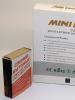
There is no box of any sort. It comes wrapped in bubble wrap:
We unfold the film and look at the package:

The case itself consists of two aluminum halves. No roughness, burrs, etc. I did not find - the workmanship is at the level.
The module with the screen, buttons and infrared port is packed in a separate layer of bubble wrap with additional padding for softness.
The kit also contains: a protective glass (plastic) in a shipping film, a set of screws and fittings for fastening, a hex key, 6 round metal buttons.
Let's take a closer look at the screen: 
As I wrote above, this is an obvious clone of the old, but still produced and sold display module, only slightly modified.
The buttons in the original module are located below the screen, in the Chinese counterpart - on the side.
The original buttons are made of plastic, in the Chinese analogue they are made of metal. I don’t know how much this affects their durability, but they definitely click louder and more clearly than we would like :).
In addition, an IR receiver has been added to the analog (a black "light bulb" in the upper left corner), as well as an output of 4 GPIO pins on the bottom side: 
Most importantly, despite all the modifications, the original drivers from Adafruit are still suitable for this module, the installation of which even a beginner in Linux systems can master.
Let's start assembling: 
We place the "raspberry" in the lower half of the body. In some aluminum cases, there are pins that, resting against the SoC and the memory chip, remove heat from them, thereby the case acts as a heatsink.
None of this applies to this body. Therefore, you need to have radiators. These copper ones have proven themselves well. 
We fix the "raspberries" with fittings. 
We put a module with a screen, buttons and an IR receiver on top. 
We prepare the upper half of the case: we bait the buttons into the holes, put the protective glass in place.
Estimate the thickness of the partitions that separate the USB ports from the main part of the internal space of the case. The manufacturer obviously did not spare the material. 
We connect both halves of the case and tighten the complete screws with the complete hexagon. 
The final touch: a sticker on the bottom of the rubber feet case. By the way, pay attention to the notch for microSD. It is made in a human way, and the memory card can really be pulled out with a finger. In many acrylic cases, including the case that I had earlier, although there was a hole for accessing the memory card, in fact this card had to be scratched out every time with tweezers. 
Housing assembled. View from different angles :).
Setting
After assembling the case, you need to configure 3 components separately: display, buttons and IR receiver.Display

Sorry for the picture quality, but that's the only way I managed to take a picture.
Of course, in reality, the display does not “bluish”, but adequately conveys all colors. And of course, it is not needed in order to work with him in Raspbian. The Raspbian GUI is generally not designed for screen resolutions below 800x480.
The shell of the Squeezebox audio player (see the picture in the review header - this is it), a portable retro console, a smart home interface or a self-written interface for quick access to the functions of some other DIY project based on the Raspberry Pi - this is the scope of such displays .
Display setting
Installing drivers from Adafruit:
sudo echo "deb http://apt.adafruit.com/raspbian/ wheezy main" >> /etc/apt/sources.list sudo wget -O - -q https://apt.adafruit.com/apt.adafruit. com.gpg.key | apt-key add - sudo apt-get update sudo apt-get install node sudo apt-get install occidentalis sudo apt-get install raspberrypi-bootloader sudo apt-get install adafruit-pitft-helper
Activate the display:
sudo adafruit-pitft-helper -t 22
The setup wizard will ask if you need to display the console (should) and if you need to put a shutdown button on the 23rd pin of the GPIO. GPIO pin 23 is, if I'm not mistaken, the topmost button near the display, marked with a circle. If you do not plan to use the buttons for other purposes, then you can agree to the proposal of the setup wizard, and then you will have a physical button to complete the work and turn off the "raspberry".
Now let's create a config for the windowed GUI:
sudo nano /usr/share/X11/xorg.conf.d/99-pitft.conf
You need to enter in it:
Section "Device" Identifier "Adafruit PiTFT" Driver "fbdev" Option "fbdev" "/dev/fb1" EndSection
And reboot:
sudo reboot
If all the steps were followed correctly, then on the 2.2 "display, first the console with the loading statuses will appear, and then the Raspbian GUI. If the console appears, but the GUI does not - check that the Raspbian settings are set to autoload to the GUI or start it manually with the command startx).
Buttons
On the available 6 buttons, you can hang any actions, depending on what task the Raspberry Pi performs.
To demonstrate their functionality, I am posting an example of their use as a mouse emulator. In this case, four buttons near the screen will be used to move the cursor along the X and Y axes, and 2 buttons on the right end emulate clicking the right and left mouse buttons, respectively.
Setting buttons on the example of a mouse emulator
Installing Python libraries for working with GPIO:
sudo apt-get update sudo apt-get install libudev-dev sudo apt-get install python-pip sudo pip install rpi.gpio sudo pip install python-uinput
Activate the uinput module:
sudo modprobe uinput
Download scripts for working with buttons:
mkdir Python-keys cd Python-keys wget www.raspberrypiwiki.com/images/6/6c/Python-keys.zip unzip Python-keys.zip
Let's run the script:
sudo python rpi-2.2TFT-mouse.py
IR receiver
With the IR receiver, the situation is the same as with the buttons: theoretically, each key on the remote control can be assigned to execute any command.I am publishing a quick guide to setting up an IR receiver.
Setting up the IR receiver
Install the LIRC package:
sudo apt-get install lirc liblircclient-dev
Let's edit the configuration file:
sudo nano etc/lirc/hardware.conf
Its lines should look like this:
LIRCD_ARGS="--uinput" LOAD_MODULES=true DRIVER="default" DEVICE="/dev/lirc0" MODULES="lirc_rpi"
Editing the config.txt file:
sudo nano /boot/config.txt
You need to find the lines in it:
# Uncomment this to enable the lirc-rpi module #dtoverlay=lirc-rpi
And bring them to the following form:
# Uncomment this to enable the lirc-rpi module dtoverlay=lirc-rpi,gpio_in_pin=26
After these steps, you need to reboot:
sudo reboot
Now let's check if the infrared port is working:
sudo modprobe lirc_rpi sudo /etc/init.d/lirc stop sudo mode2 -d /dev/lirc0
Here you need to direct the remote control towards the IR receiver and press the buttons. If the IR receiver is working correctly, we will see something like this: 
We interrupt the execution of the command (Ctrl + C on the keyboard) and launch the configuration wizard:
sudo /etc/init.d/lirc stop sudo irrecord -n -d /dev/lirc0 ~/lircd.conf
The remote control setup wizard will start, which will prompt you to sequentially press all the buttons on the remote control - so that each of them is pressed at least once. Each button "caught" by the IR receiver will be displayed as a new dot on the screen.
After completing these steps, the setup wizard will generate a config and put it in the user directory. Let's make this config the default config:
sudo cp ~/lircd.conf /etc/lirc/lircd.conf sudo /etc/init.d/lirc start
This completes the setup.
About how the built-in Wi-Fi works
To my surprise, it turned out that the case has almost no effect on Wi-Fi.The built-in raspberry adapter works equally bad both in the case and without it.
Here are my speed measurements:

In both cases, the "raspberry" was in the same room as the router. In general, the Internet continues to work even in an aluminum case, but if you need high speed, then you need to connect to the network via Ethernet, and not via Wi-Fi.
About how the Raspberry Pi heats up in this case
Another important issue is the heating of the "raspberry" in a deaf metal case.According to my measurements, the temperature of the processor in low-load mode fluctuated around 46.7 ° C - 48.3 ° C. The low-load mode of operation is when I dig into the console, install and update packages, deal with drivers.
Also did a stress test.
How to do a stress test
Installing the stress testing package:
sudo apt-get install stress wget https://raw.githubusercontent.com/ssvb/cpuburn-arm/master/cpuburn-a53.S gcc -o cpuburn-a53 cpuburn-a53.S
Test run:
while true; do vcgencmd measure_clock arm; vcgencmd measure_temp; sleep10; done& stress -c 4 -t 900s
In the stress test mode, the raspberry processor gets 100% load within 15 minutes. The temperature is displayed every 10 seconds.
The critical temperature for "raspberries" is 80 ° C - when this value is reached, the so-called. throttling - lowering the frequency of the processor in order to avoid further temperature rise and damage from overheating.
With my radiators, "raspberry" passed the test on the brink.
At first, the temperature jumped quite sharply from 46°C to 68°C, in just a couple of minutes.
After that, she continued to slowly rise, and in the last minutes she crawled up to 80.1 ° C. But throttling did not start - the test ended before the temperature had time to finally cross this mark.
After completion of the test, the temperature dropped from 80°C to 72°C in a minute, and in the next 10 minutes it dropped to 50°C.
The body is noticeably hot. I didn’t burn my hand, but it was very warm, so to speak.
I am pleased with the results. Still, in normal operation, there are no moments when the Raspberry processor is stably loaded at 100% for a long time. So overheating when using this case can not be particularly feared.
Useful little things
gpio -g mode 27 out - disable display backlightgpio -g mode 27 in - turn display backlight back on
The IR receiver is connected to GPIO pin 26.
- simple menu adapted to small screens and low resolution.
- tiled menu, also adapted to small screens with low resolution.
Conclusion

Here is such a body. Personally, I am pleased with the acquisition, the quality of its workmanship is simply excellent. If I get another Raspberry Pi, then most likely I will buy another copy of this case already “for my own”.
Its disadvantages include the work of four buttons near the screen - they click louder than we would like (this is noticeable in the video with a demonstration of the work). I don't know, maybe it will be possible to somehow rustle them with rubber gaskets.
The rest of the impressions were only positive. Functional and well made item.
The price bites a little, yes.
But GearBest generated a coupon LCDS, with which this case can be purchased at a discounted price of $35.99.
The product was provided for writing a review by the store. The review is published in accordance with clause 18 of the Site Rules.
I plan to buy +32 Add to favorites Liked the review +38 +71I continue to publish a series of articles about mastering the Raspberry Pi and Arduino.
Today's article is about connecting a TFT touch display to a Raspberry Pi.
For the “raspberry”, a great many different touch displays are produced and sold, but there are no special differences between them. It is based on the time-tested line of displays from Waveshare Electronics, which is copied and produced using the same components under its own label by other Chinese manufacturers.
TFT display: overview and connection
TFT displays for Raspberry Pi can be divided into 3 varieties:
- connected via DSI interface (15-pin flat cable connector)
- connected via HDMI
- connected via GPIO
Most displays with a small diagonal (up to 4 inches) are connected via GPIO and are a printed circuit board on which the TFT module itself is fixed, the adapter and the GPIO connector for connection are soldered.
Such boards in the Raspberry Pi environment are usually called HAT: Hardware Attached on Top, which means “equipment connected from above”.
Short review
The module I bought, manufactured by the Chinese company Keyes (not to be confused with the Chinese one - these are different companies) is a HAT board made of red textolite.
On top of it is a 3.2″ touchscreen display with a resolution of 320 × 240 pixels - like on old smartphones from the mid-zero years, as well as 3 physical buttons.
The display module involved is called INANBO-TP32D, but knowing this detail is of no practical use.

On the reverse side is a 26-pin GPIO slot for connecting the board to the Raspberry Pi. You can also see the DSI interface with a cable from the TFT module already connected to it, some kind of controller and other small details.
In fact, the board is an adapter that should make friends with a specific TFT module with specific specifications, a touch interface and hardware buttons with “raspberry” via GPIO.

Connecting the display to the “raspberry” is very simple - we combine the connector located on the HAT-board with the GPIO pins, starting from the outermost ones.
I had to pull my Raspberry Pi 3 out of the case - otherwise the board would not sit on the pins, resting its “horns” against the side walls. In general, these horns are bare textolite, so you can carefully cut them off with a jigsaw and then the board will fit perfectly into the case. But I did not see the point in such an action, and further I will explain why. Also, I have not yet begun to remove the protective film - it looks somewhat sloppy in the photo, but does not interfere with working with the display.

When power is applied to the Raspberry Pi, the display will glow solid white, but no image will appear on it. It's okay, that's how it should be. A white glow indicates that the display is working properly, is properly connected and is receiving power from the GPIO. But to display an image on it, you will need to download and install drivers.
Driver installation
Googling “Raspberry Pi display drivers”, I first came across some scary and cumbersome manuals that recommended downloading some files from a git repository, then installing them somewhere, then manually editing the configuration files and manually set the correct screen resolution by editing other files.
Perhaps, once these instructions were really relevant, and for the sake of connecting an external display, you had to go through such torment.
But at the moment, installing drivers for a TFT display for Raspberry Pi is no more complicated than the process of physically connecting the display to a microcomputer, and will take no more than 5 minutes of time.
First of all, you need to download the archive with the driver (LCD-show-161112.tar.gz) from this page .
Then unpack it using the console command:
Tar xvf LCD-show-161112.tar.gz
Let's go to the directory with the unpacked driver:
CD LCD-show/
And run the script that will do the rest of the work:
./LCD32-show
Please note that this script is designed to work with a 3.2″ display - like mine. Therefore, to work with displays of other diagonals, you will need to run other scripts: LCD28-show, LCD35-show, LCD4-show, LCD4-800×480-show, LCD43-show, LCD5-show, LCD7-800×480-show, LCD7- 1024×600-show, LCD101-1024×600-show.
All of them are bundled with the above driver, and which script is intended for which display is clear from the names.

If everything is done correctly, then after running the script, the Raspberry Pi will start to reboot, and an image will appear on the display.
To switch back from a TFT touch display to an HDMI monitor, you need to go back to the driver folder from the console:
CD LCD-show/
And activate the script:
./LCD HDMI
After that, the “raspberry” will reboot again, the screen will turn white, and the image will be displayed on the monitor connected via HDMI.
The driver also allows you to flip the image 90, 180 and 270 degrees:
Cd LCD-show/ ./LCD32-show 90
After rebooting, the TFT display will be rotated 90 degrees.
cd LCD-show/ ./LCD32-show 180 cd LCD-show/ ./LCD32-show 270
These commands rotate the image by 180 and 270 degrees respectively.
Cd LCD-show/ ./LCD32-show 0
Return to the default screen orientation.
The touch interface does not need to be configured separately - it is already registered in the driver and is activated by default.
The issue with the physical buttons that are present on some screen modules remains unresolved. I have left it unattended for now, because I did not see the point in having these buttons for myself. What actions should I hang on them, and, most importantly, why?
TFT display for Raspberry Pi 3 in action
The catch is that the Raspbian GUI is not designed to run at 320x240.

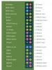
This is what the Raspbian PIXEL desktop looks like. I set in advance in the interface settings the smallest possible size of shortcuts in the taskbar - otherwise, at such a low resolution, they overlap each other.

We open the menu. More or less tolerable, although of course it's not normal when the menu takes up more than half the width of the screen.

Let's open the Chromium browser. Everything! Labels and fonts in the taskbar moved out and climbed on top of each other - reducing their size to the smallest possible did not help. The browser itself is absolutely not adapted to this screen resolution, and surfing sites is almost impossible. That is, it seems to be there, but the need to constantly scroll web pages not only vertically, but also in the horizontal direction makes this exercise meaningless.

But it is quite possible to work with the console. Here low resolution is not a hindrance. And if you unload from the GUI at all, then using the console will become even more convenient.
Conclusion
The small plug-in TFT displays for the Raspberry Pi are great for field console use and can replace a conventional full-size monitor.
They can also be used in Raspberry Pi-based DIY devices (smart home, media center, 3d printer, CNC machine) to display information and control through a graphical interface specially designed for low resolution and small diagonal.
But they are not suitable for working in Raspbian PIXEL due to the lack of adaptation to resolutions below 1024x600 in this GUI.
I have no complaints about the quality of the display reviewed in this article. But at the moment I just have nowhere to apply it, so he goes to rest on the shelf. I plan to use it in the future in the “smart home” device.
After you bought and unpacked the raspberry pi 3 model b, the question will appear:
How to connect "raspberry" to a monitor or TV?

The raspberry pi 3 has an HDMI digital video output and you can connect your computer to the monitor using an HDMI to HMDI cable if your monitor or TV has an HDMI connector.
How to connect "raspberry" to a monitor or TV?

If the monitor or TV has connectors, as in the picture - HDMI, DVI, D-sub, there is a choice through which type of connector to connect.
how to connect raspberry pi
Via HDMI: All you need is a cable. Data transmission through this interface allows the transmission of high-resolution digital video data and multi-channel digital audio signals.
Via DVI: You need a DVI-D to HDMI adapter and an HDMI to HDMI cable. Data transmission through this interface allows you to transmit video signal to digital devices such as LCD monitors, TVs and projectors.
Via D-SUB: You need a D-SUB and hdmi adapter, as well as a d-sub to d-sub cable. This type of connector is widely used in computer technology. This is a fifteen-pin interface for connecting VGA (SVGA) monitors.
Adapters:

adapter D-SUB and hdmi
With d-sub hdmi adapter. Since the conversion of a digital signal into an analog one is carried out by a microcircuit (which one is not known), only resolutions are guaranteed: 1440x900 60 Hz and 1280x1024 75 Hz. Higher 1920x1080 60 Hz is not a fact, it all depends on the adapter model and how lucky you are.
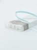
The monitor comes with a U-shaped HDMI-HDMI adapter, a stylus and brass stands with screws.
There is a switch on the back of the screen, slide it closer to the micro-usb connector.
Hello.
I have already written about on the Raspberry Pi without graphics and about . Now we will install the OS RASPBIAN JESSIE with graphics and connect a 5-inch screen with a touchscreen, which can be purchased at the chip and dip store for 4000 rubles.
Plus, we will install a full-fledged Kodi media center on top of the main OS for easy viewing of video content. That is, to switch between RASPBIAN and
Unpack the image that will weigh 4
more than GB.
SD- the card is best to use at least 8GB and preferably a good quality well-known brand (I have a Transcend Premium 400x). The speed of the raspberry greatly depends on this.
How to put an image on a USB flash drive is written in the previous one, starting from and to the chapter " launch". After completing the steps described there, do not remove the card and return here.
Now you need to find and edit the file config.txt (if you work in windows, then be sure to download the Notepad ++ text editor and do everything in it).
In windows this file is located at the root of the drive (in fact, this is a boot partition, about 100MB. It is marked as FAT32. The other part of the flash drive is marked in ext4 and windows simply does not see it) on which the image was recorded ...
... and in on the boot partition.
The markup of the card is as follows: the first partition (boot) is created for boot files and formatted in FAT32, 100MB in size, and the second partition is formatted in ext4 for a file system, about 5GB in size. At the first start, the file system is automatically expanded to the entire remaining space of the card (in previous releases, this was done manually).
Well, I digress…
Opening the file config.txt and find the lines there:
# uncomment to force a specific HDMI mode (this will force VGA) #hdmi_group=1 #hdmi_mode=1
We change them like this:
# uncomment to force a specific HDMI mode (this will force VGA) hdmi_group=2 hdmi_mode=1 hdmi_mode=87 hdmi_cvt 800 480 60 6 0 0 0
So far, that’s all with this file, now the raspberry will start up with our monitor (without these lines, there would be only ripples on the screen).
We save the file, disconnect the card, take it out of the computer and insert it into the RPI.
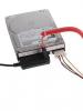
We collect a "sandwich" from the screen and raspberries (so that the HDMI connectors match), insert the HDMI adapter (he enters tightly), and supply power to the RPI and to the screen (that is, you need to stock up on two wires with micro-usb and two power supplies). Yes, don't forget to connect your keyboard and mouse.
PSU for raspberries should be about 2 amps, and one is enough for the screen. If there is not enough power, then an icon with a yellow lightning bolt will appear on the screen.
If the raspberry is overheated, a thermometer will appear on the screen.
After the start, a multi-colored square will appear on the screen, and then an inscription on a white background, indicating that the file system has been extended to the entire remaining space of the card. Next, four raspberries will appear in the left corner and various lines will run, then the screen will darken for a few seconds and the desktop will appear ...
Your data:
login- pi
password- raspberries
A small digression: firstly, the touchscreen does not work for you yet, and secondly, if during operation the window does not fit on the screen and no buttons are visible, then you need to hold down the left alt and drag the window to any place with the mouse.
First you need to configure the system.
You can do this by opening a terminal and typing commands there. (although this is not very convenient because it is small).
Or connect via ssh (login and password are written above). I will do it via ssh and I advise you to do the same.
So, we enter the command:
sudo raspi-config
We ignore the first point since the file system has already been expanded automatically. You can verify this by opening another terminal and giving the command:
The second point - changing the password, remains at your discretion.
We do not touch the third and fourth points.
Open the fifth item and select Change Locale
If you want to return to the previous window, click Esc.
Scroll down arrow to ru_RU.UTF-8 UTF-8, put an asterisk with a space and press Enter.
In the next window select ru_RU.UTF-8 and again we press Enter.
We return to the fifth point and go to Change timezone, choose Europe and click Enter.
Choose your city and click Enter.
Again we return to the fifth point and go to Change Keyboard Layout, choose Generic 105-key (Intl) PC and click Enter.
In the next window select Other and click Enter.
Turn the arrow to Russian and click Enter.
In the next window, scroll up to Russian and click Enter.
In the next three windows, just click Enter.
Now with a key Tab select " Finish"and press Enter.
This completes the basic configuration. (you can return to it any time you want), reboot the system with the command:
Now about updates.
Update the repositories with the command...
Sudo apt update
… But do not update the system - sudo apt upgrade, if this is done, then problems with the touchscreen, keyboard layouts and something else will begin.
Sudo apt install synaptic mc
Install xscreensaver Without which the screen will go out after 10 minutes.
sudo apt install xscreensaver
What else to install decide for yourself.
Now you need to display the keyboard layout icon on the top panel. If this is done by regular means, then it will work until the first reboot. Therefore, we will go the other way.
Installing the program gxkb
sudo apt install gxkb
Adding gxkb to autoload:
Nano /home/pi/.config/lxsession/LXDE-pi/autostart
After all the lines you need to enter this - @gxkb
Save and close the file.
The choice of key combination for switching is done in the file - /home/pi/.config/gxkb/gxkb.cfg, by default it is indicated there alt_shift, I forwarded to ctrl_shift:
Nano /home/pi/.config/gxkb/gxkb.cfg
Save, close the file and reboot.
touchscreen
Download the archive to your home folder:
Cd /home/pi wget https://site/file/LCD-show-161112.tar.gz
The archive was taken.
Unpacking it:
Tar xvf LCD-show-161112.tar.gz
You will have an LCD-show folder that you need to go to...
And run the script:
Sudo ./LCD5-show
After that, the raspberry will immediately reboot and come to life with a working touchscreen. If the positioning accuracy suits you, then you can not calibrate anything.
If calibration is needed, then go to the LCD-show folder ...
Cd /home/pi/LCD-show
And install the package xinput-calibrator_0.7.5-1_armhf.deb
sudo dpkg -i -B xinput-calibrator_0.7.5-1_armhf.deb
The same can be done in the "Explorer" by right-clicking on the package and selecting "Install Packages".
Now go to the program menu, to the section in the "Options" section and select "Calibrate Touchscreen". After an accurate hit on all four targets, settings will appear that need to be written to a file /etc/X11/xorg.conf.d/99-calibration.conf.
We launch another terminal, open the file there ...
Sudo nano /etc/X11/xorg.conf.d/99-calibration.conf
... and remove everything from it.
We return to the window with the calibration data, copy the “InputClass” section and paste it into the previously opened and emptied file.
Section "InputClass" Identifier "calibration" MatchProduct "ADS7846 Touchscreen" Option "Calibration" "171 3957 174 4042" EndSection
You have your numbers.
To add a "right mouse button" you need to do this:
Section "InputClass" Identifier "calibration" MatchProduct "ADS7846 Touchscreen" Option "Calibration" "171 3957 174 4042" Option "EmulateThirdButton" "1" Option "EmulateThirdButtonTimeout" "550" Option "EmulateThirdButtonMoveThreshold" "50" EndSection
For the context menu to appear, you need to hold the stylus for about half a second. The last option is apparently the jitter threshold.
Save the file, close and reboot. Now everything will be correct.
Because the calibrator makes small changes to the file config.txt (which we corrected on the computer), it is worth saying a little about it. This is the file in which the start settings are located, open it and see:
sudo nano /boot/config.txt
Our edits disappeared and appeared at the end, with another line:
# Enable audio (loads snd_bcm2835) dtparam=audio=on hdmi_group=2 hdmi_mode=1 hdmi_mode=87 hdmi_cvt 800 480 60 6 0 0 0 dtoverlay=ads7846,cs=1,penirq=25,penirq_pull=2,speed=50000,keep_vref_on =0,swapxy=0,pmax=255...
We will also add...
Finding the lines:
# uncomment to force a console size. By default it will be display "s size minus # overscan. #framebuffer_width=1280 #framebuffer_height=720
And we do them like this:
# uncomment to force a console size. By default it will be display "s size minus # overscan. framebuffer_width=800 framebuffer_height=480
Below we find this:
# uncomment if hdmi display is not detected and composite is being output hdmi_force_hotplug=1
And add three lines:
# uncomment if hdmi display is not detected and composite is being output hdmi_force_hotplug=1 hdmi_ignore_cec_init=1 hdmi_ignore_cec=1 gpu_mem=256
You can try to allocate more video memory - gpu_mem=512.
If you want to increase the current supplied to usb, then add a line somewhere:
Max_usb_current=1
But here you need to understand that if you connect powerful consumers, then the current of the raspberry itself may not be enough, which is expressed in unstable operation.
Save the file and reboot.
The described settings are quite enough for the normal operation of RPI, but I recommend reading about the various parameters of this config here.
WiFi and Bluetooth
If you want to disable wifi and / or bluetooth, then you need to create a file - /etc/modprobe.d/raspi-blacklist.conf
sudo nano /etc/modprobe.d/raspi-blacklist.conf
And paste this into it:
#wifi blacklist brcmfmac blacklist brcmutil #bt blacklist btbcm blacklist hci_uart
So wifi and bluetooth are disabled.
And so only wifi is disabled:
#bt blacklist btbcm blacklist hci_uart
Install:
sudo apt-get install samba samba-common-bin
Backup config:
Sudo mv /etc/samba/smb.conf /etc/samba/smb.conf.bak
We create our own:
sudo nano /etc/samba/smb.conf
Content:
Workgroup = WORKGROUP netbios name = RaspberryPi server string = share security = user map to guest = bad user browseable = yes path = /home/pi/papka writeable = yes browseable = yes guest ok = yes
Save and close.
Create a folder for samba:
Mkdir /home/pi/folder
Let's give her permission:
sudo chmod -R 777 /home/pi/papka
Restart samba:
sudo /etc/init.d/samba restart
Set to guest login (come whoever you want) and read-write.
Kodi media center
Create an "input" group if it doesn't exist:
sudo addgroup --system input
Install Kodi:
sudo apt-get install kodi
After installation, we do not launch anything.
Create a file - /etc/udev/rules.d/99-input.rules
sudo nano /etc/udev/rules.d/99-input.rules
And add the following to it:
SUBSYSTEM==input, GROUP=input, MODE=0660 KERNEL==tty*, GROUP=tty, MODE=0660
Save and close.
Create another file - /etc/udev/rules.d/10-permissions.rules
sudo nano /etc/udev/rules.d/10-permissions.rules
# input KERNEL=="mouse*|mice|event*", MODE="0660", GROUP="input" KERNEL=="ts*|uinput", MODE="0660", GROUP="input" KERNEL== js*, MODE=0660, GROUP=input # tty KERNEL==tty*, MODE=0666 # vchiq SUBSYSTEM==vchiq, GROUP=video, MODE=0660
Save and close.
sudo usermod -a -G audio pi sudo usermod -a -G video pi sudo usermod -a -G input pi sudo usermod -a -G dialout pi sudo usermod -a -G plugdev pi sudo usermod -a -G tty pi
sudo nano /etc/rc.local
It will turn out like this:
Save and close.
We reload the raspberry for the changes to take effect.
Now in the program menu in the "Audio and Video" section we find "Kodi Media Center" and start ...
You will see how the image blurs and turns into a striped frog. This will happen for a couple of minutes, and then the picture will appear. In the middle there will be a window offering to disable incompatible repositories - click Yes.
I have to warn you right away that the touchscreen in Kodi does not work correctly, we can say that it does not work at all. I don't know how to solve this problem yet. Therefore, we only have a mouse and keyboard at our disposal.
Now let's set up Kodi. Click the button SYSTEM, then Appearance and finally International. Click language and select Russian language (English).
Next, click on the icon with the house at the bottom right, click the big button SYSTEM, and then the small one on the left - "System". Select "Audio output" and under "Audio output device" select - PI: Analogue. After that, Kodi will start normally without any stripes on the screen.
The fact is that before our changes, both sound and video went through the HDMI channel, and the result was “porridge”. Now only video goes through HDMI, and sound through the headphone jack.
Now again click on the icon with the house, then the shutdown button (bottom left), and then "Exit". Most likely you will see a frozen black screen, so reboot the raspberry by turning off the power.
After the reboot, start Kodi again, now there will be no stripes anymore. It remains only to make sure that the player does not freeze when exiting.
To do this, create a script - /usr/local/bin/ startkodi
Sudo nano /usr/local/bin/startkodi
Content:
#!/bin/bash fbset_bin=`which fbset` xset_bin=`which xset` xrefresh_bin=`which xrefresh` if [ ! -z $fbset_bin ]; then DEPTH2=`$fbset_bin | head -3 | tail -1 | cut -d " " -f 10` fi kodi " [email protected]" if [ ! -z $fbset_bin ]; then if [ "$DEPTH2" == "8" ]; then DEPTH1=16 else DEPTH1=8 fi $fbset_bin -depth $DEPTH1 > /dev/null 2>&1 $fbset_bin - depth $DEPTH2 > /dev/null 2>&1 fi if [ ! -z $xset_bin ] && [ ! -z $xrefresh_bin ]; then if [ -z $DISPLAY ]; then DISPLAY=":0" fi $xset_bin -display $DISPLAY -q > /dev/null 2>&1 if [ "$?" == "0" ]; then $xrefresh_bin -display $DISPLAY > /dev/null 2>&1 fi fi VT="$(fgconsole)" if [ "$VT" ]; then sudo chvt 7 sudo chvt "$VT" fi
Save, close and give the script permissions:
sudo chmod a+x /usr/local/bin/startkodi
Now in the terminal, issue the command:
Now the "exit" will work as it should.
Running the script through the terminal is not convenient, so it needs to be added to the program menu. Go to the menu, in the "Options" item, find "Main Menu Editor" and run it. Select "Audio & Video" on the left and click the "Create Item" button on the right.
In the window that appears, opposite Name: write MyKodi and vice versa command: write startkodi.
Click OK, a new item will appear in the list - MyKodi
Click again OK.
Now to launch the media center, in the "Audio and Video" menu there is a button MyKodi.